Simple Beam Analysis using Karamba3D
-
Intro
-
Workflow
-
Step 1: translate rhino geometry to structural elements
-
Step 2: Specify Cross Section
-
Step 3: Specify Materials and Supports
-
Step 4: Specify Loads
-
Step 5: Assemble and Analyze the Model
-
Step 6: View Resluts
-
Conclusion
Information
| Primary software used | Karamba3D |
| Software version | 2.2 |
| Course | Simple Beam Analysis using Karamba3D |
| Primary subject | Analysis & simulation |
| Secondary subject | Structural Analysis |
| Level | Beginner |
| Last updated | March 14, 2025 |
| Keywords |
Simple Beam Analysis using Karamba3D 0/8
Simple Beam Analysis using Karamba3D
An introduction to Karamba3D for analyzing structural behavior.
Welcome to this tutorial on creating and testing the deflection of a Simple Beam using Karamba. This guide will walk you through the process of setting up a structural model, applying loads, and analyzing the beam’s behavior under various conditions. By focusing on a straightforward example, you’ll gain a clear understanding of the fundamental principles and tools needed for structural analysis in Karamba. Let’s dive in and get started!
In this tutorial, you will learn:
- Translate geometry to structural elements
- Specify cross section and material properties
- Define loads and supports
- Assemble and analyze the model
- View the results of the analysis
Simple Beam Analysis using Karamba3D 1/8
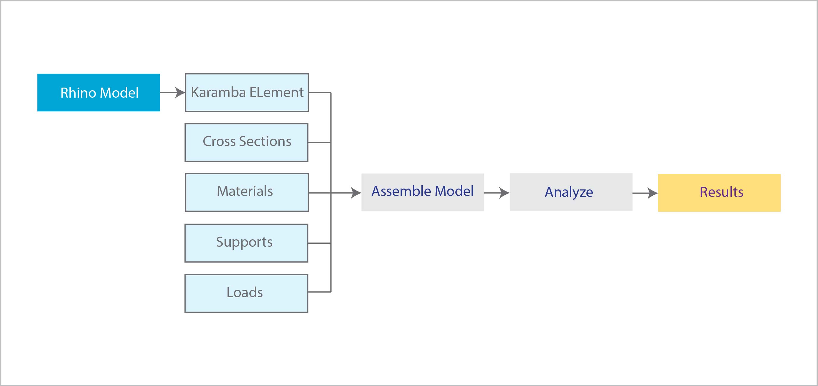
Workflowlink copied
Let’s first summarize the workflow of the analysis process. There are some basic steps that we must follow:
- Create Rhino Geometry (lines or meshes)
- Translate Rhino Geometry to Structural Elements
- Specify Cross Sections
- Specify Materials
- Specify Supports
- Specify Loads
- Assemble the Model
- Analyze the Model
- Get the Results
Simple Beam Analysis using Karamba3D 2/8
Step 1: translate rhino geometry to structural elementslink copied
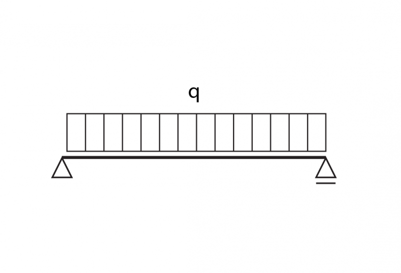
Create Rhino Geometry: Columns and Beams
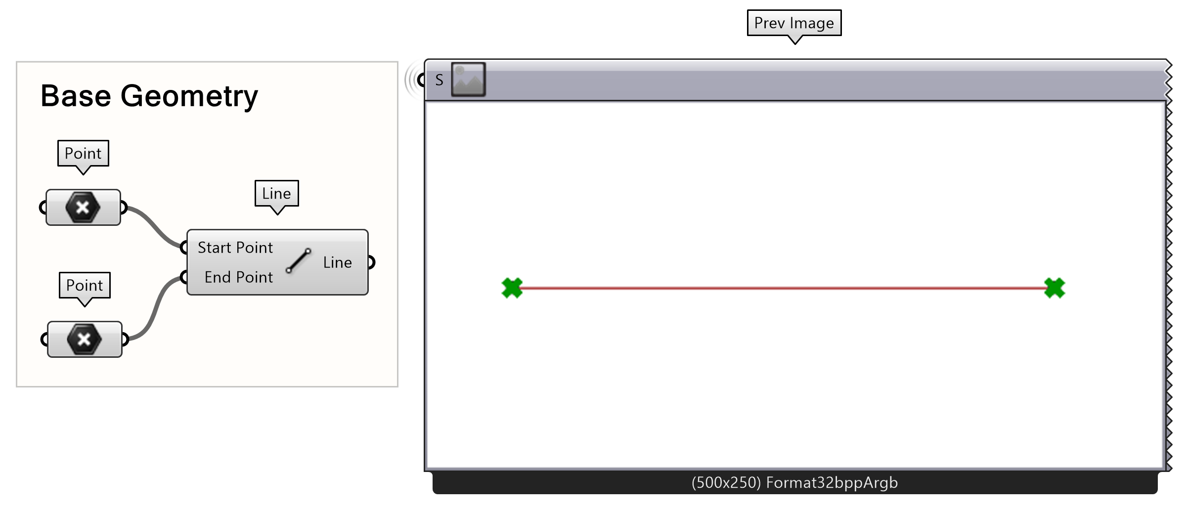
In Karamba3d solid elements such as beams and columns are represented by lines.
- Create two points in top view as shown in the image on the right and connect them to the Point parameter
- Connect the two points using the Line component
Tip: It is important to remember that the beams have to be single segment lines with two distinct endpoints
Line to Beam
All structural elements in Karamba3D are 2D dimensional. To specify the lines as columns:
- Connect the column lines to the Line to Beam component
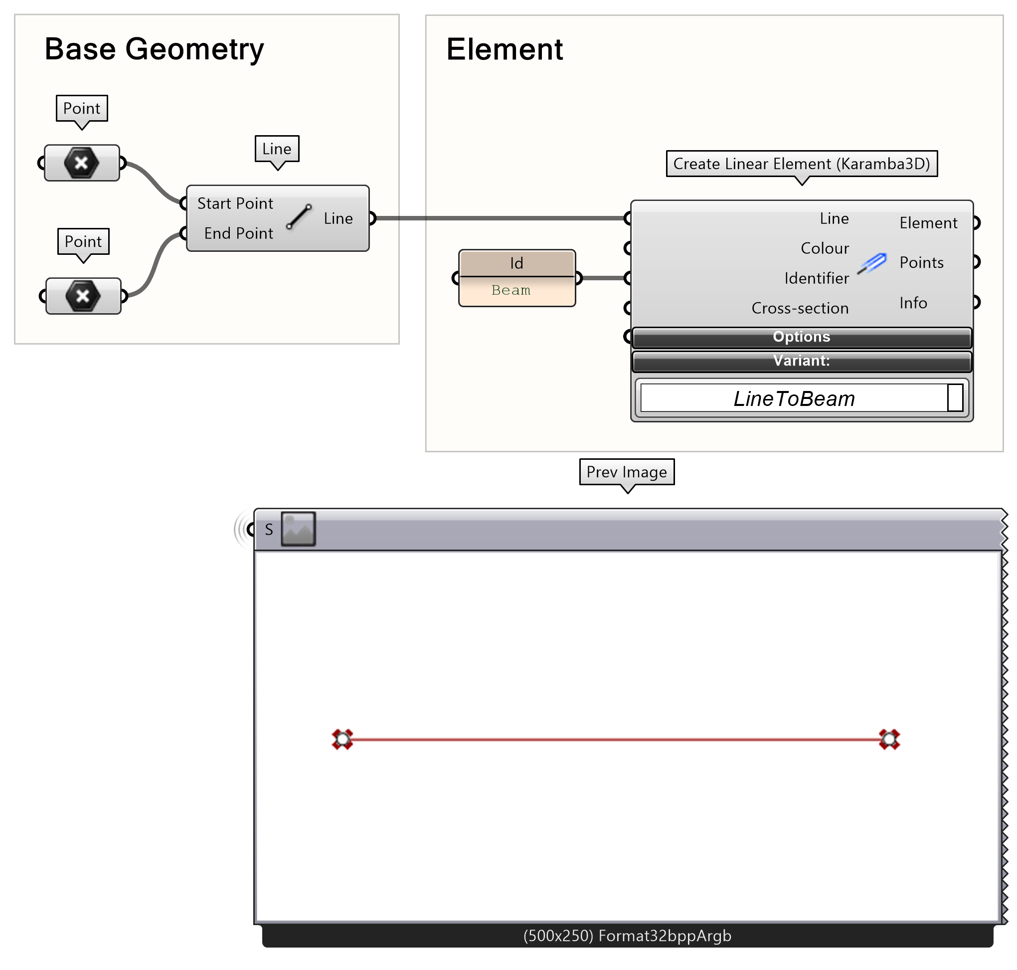
Each group of structural elements has a unique Identifier. The identifying name is important as it allows modifying specific elements or assigning properties to them and later retrieving information about their structural performance.
- Create a panel using at least one letter to specify the name of the columns. In this case it is “beam“.
- Connect the panel to the Id input in the Line to Beam component.
Tip: If we do not specify identifier by default Karamba3D will assign all properties to all the structural elements. In this example we study a single beam. Therefore, this step can be omitted. There is further elaboration on the Identifier in the following tutorial.
Simple Beam Analysis using Karamba3D 3/8
Step 2: Specify Cross Sectionlink copied
Beam Cross Section
As mentioned in step 1, in Karamba3D all structural elements are 2D dimensional. The third dimension is specified as a cross-section property. Karamba has a library of ready profiles. Through the Cross Section Range Selector, we can specify the dimension limits and select the cross section that fits our criteria:
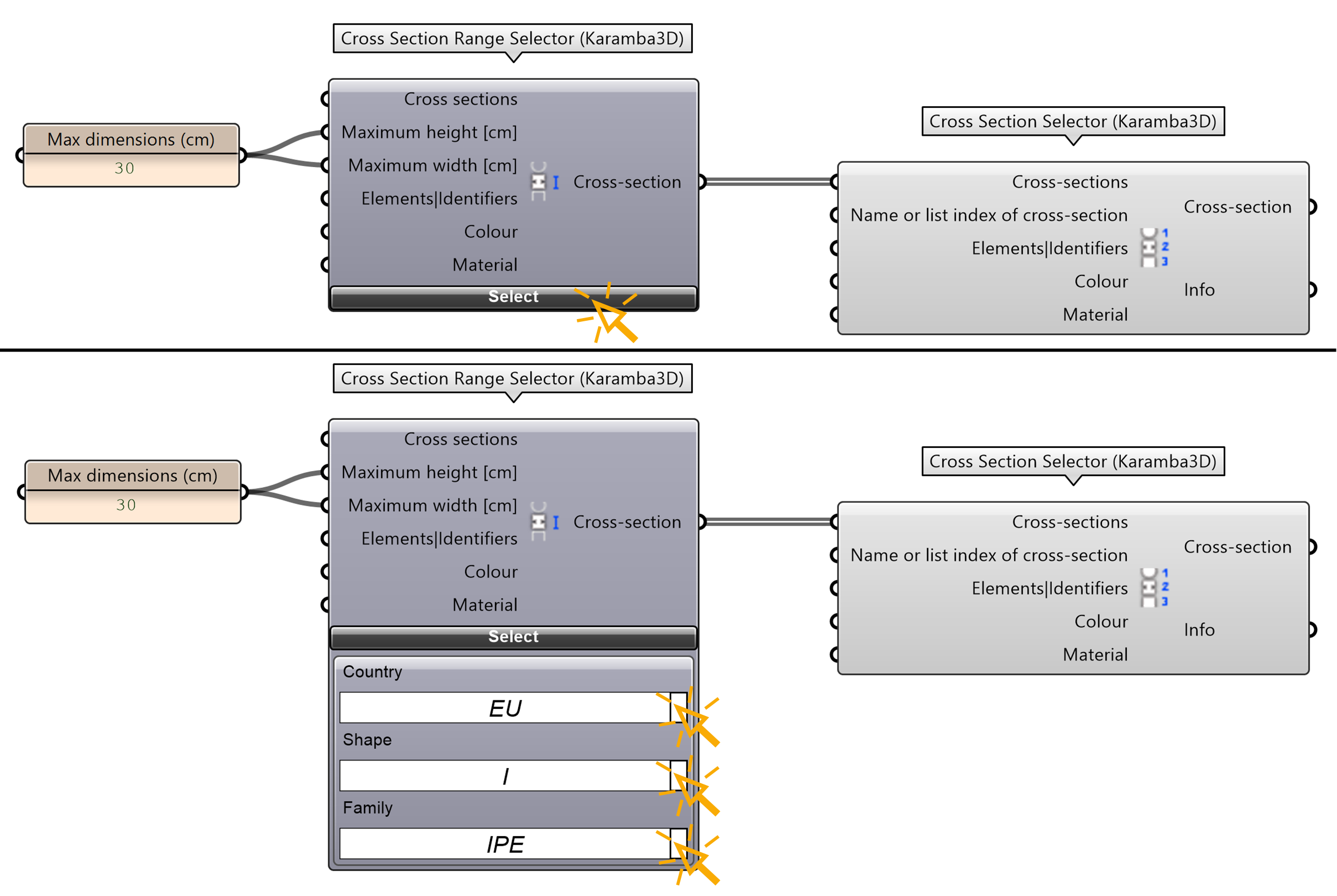
- Create a Cross Section Selector component through
- Create a Cross Section Range Selector component through
To limit the available profiles to our desired criteria:
- Specify the maximum desired height maxH and the maximum desired width maxW of the cross section.
- In the Cross Section Range Selector click the Select button.
- Choose EU from Country, I from Shape and IPE from Family
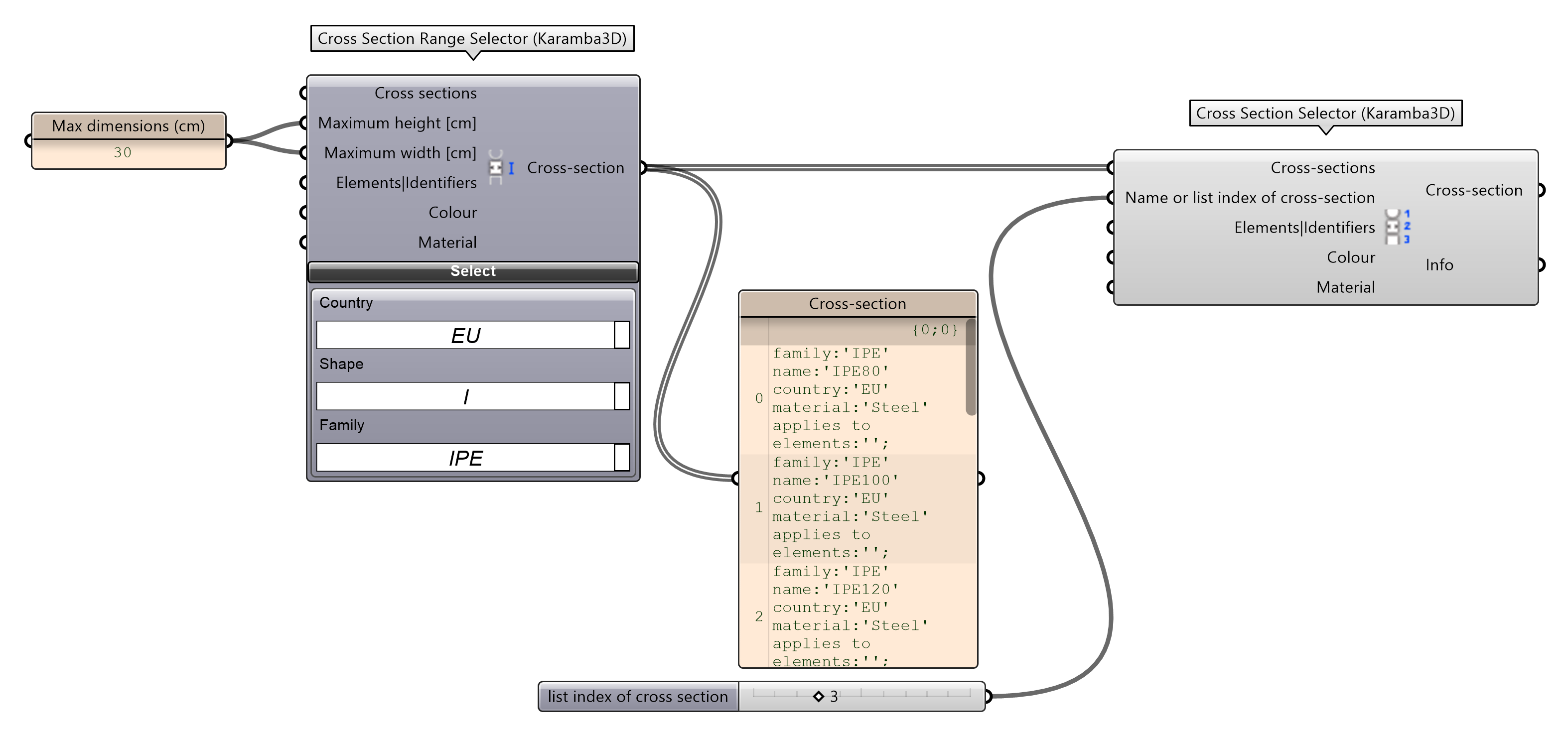
We can view the list of the IPE cross sections that meet our criteria:
- Connect a panel to CrosSec output in the Cross Section Range Selector.
For now, we can choose the third cross section in our list:
- At the Cross Section Selector connect a number slider to the Name|Ind input
Simple Beam Analysis using Karamba3D 4/8
Step 3: Specify Materials and Supportslink copied
Specifying Materials
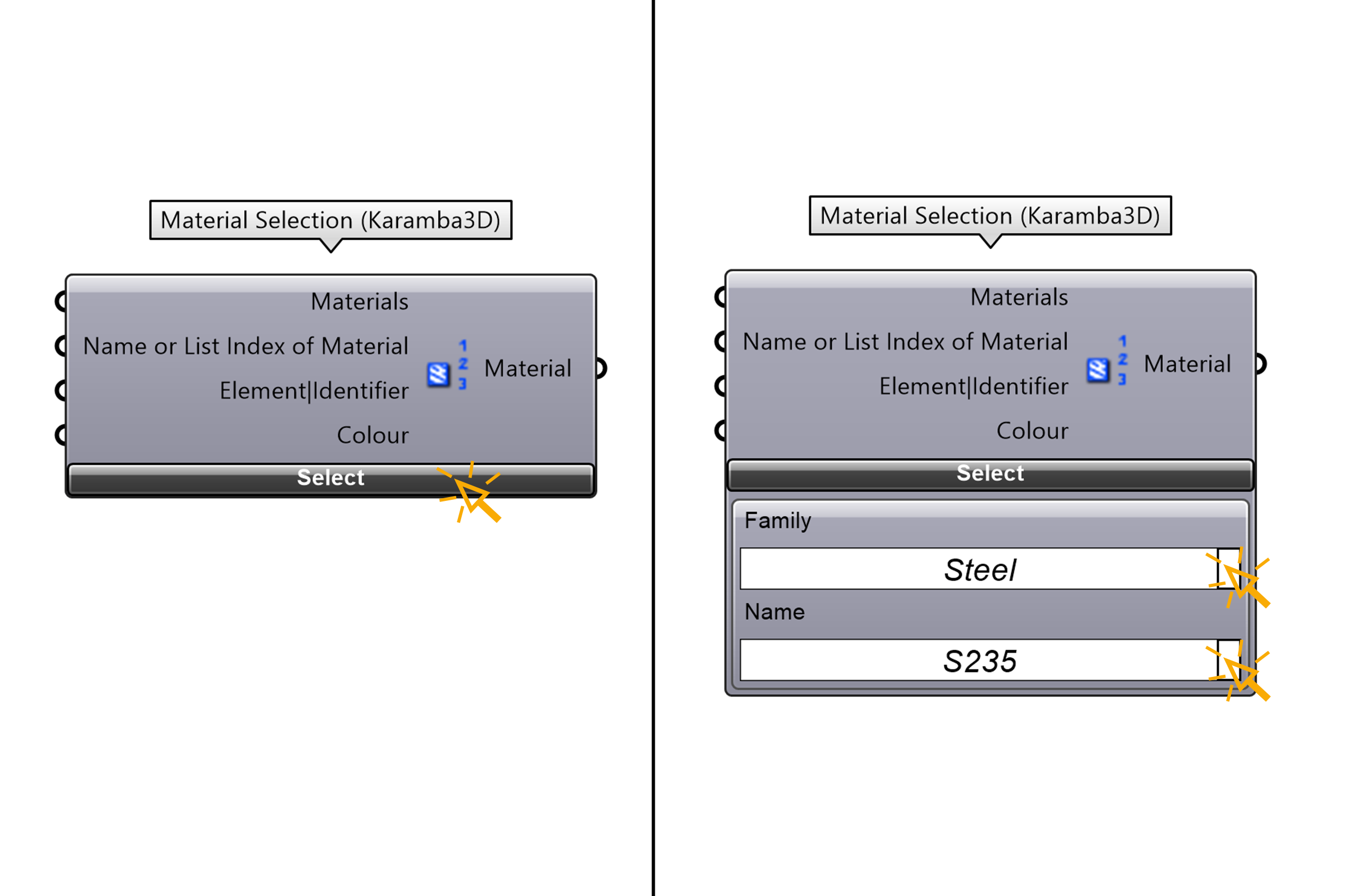
We are now going to create a steel material:
- Create a new material through
- Karamba3D offers various ready material families, let’s choose the steel family and S235 from the name list.
Specifying Supports
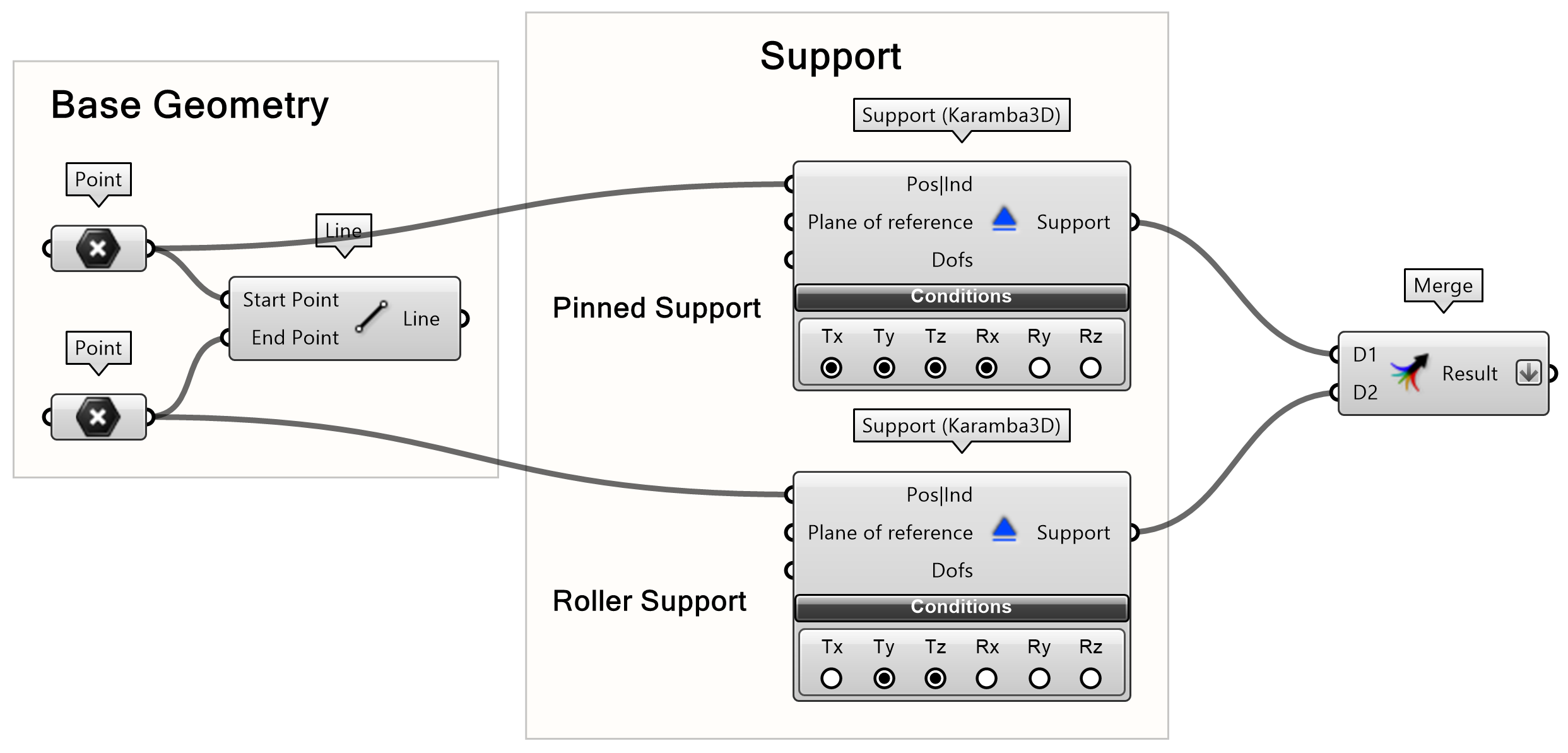
To create supports:
- Connect the points from Point parameters, representing the supports, to the Support component found at
- The support plane is by default it is the xy plane so there is no need to specify it.
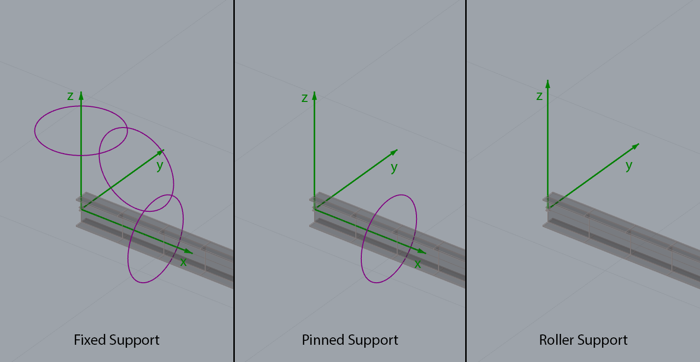
The Tx,Ty,Tz options will constrain translations in global x, y and z directions. The Rx,Ry,Rz will constrain rotations in global x, y and z axes.
- Create a pinned support by enabling Tx, Ty, Tz, Rx
- Create a roller support by enabling all Tx, Ty
Simple Beam Analysis using Karamba3D 5/8
Step 4: Specify Loadslink copied
Gravity
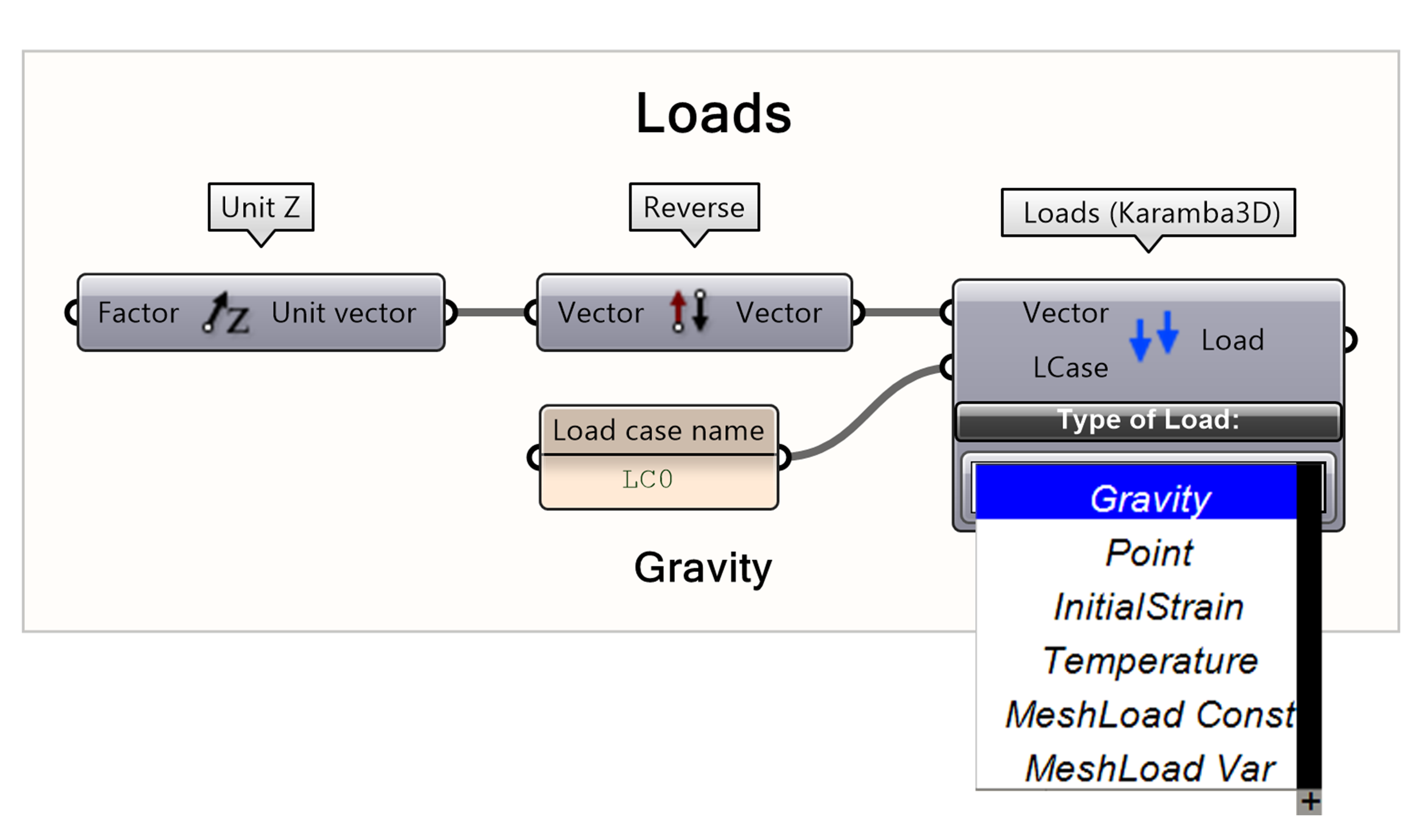
Create a load through
Specify the Type of the Load by clicking the white box and selecting Gravity.
Specify the vector of the gravity load. Gravity is negative to the global z direction therefore the vector must be reversed.
Specify the Load Case Name by connecting a panel with a unique name to LCase, in this case is “LC0”.
The Load Case input is important for retrieving results for each Load Case effect in our structure separately. For example, we may need to examine the deflection due to live loads separately from the dead loads.
Line Load
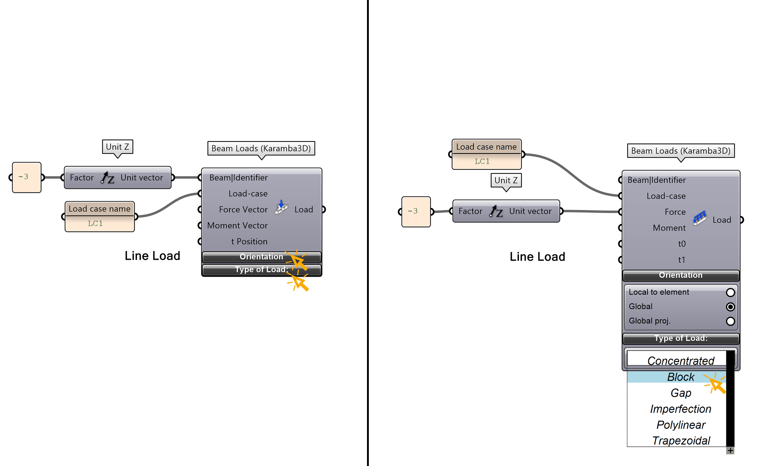
Now let’s create a live load of 3KN/m2 on the beam. For that we will use a mesh surface, and we will apply a constant load to it.
- Create another load through
- This time the Type of the Load is Block.
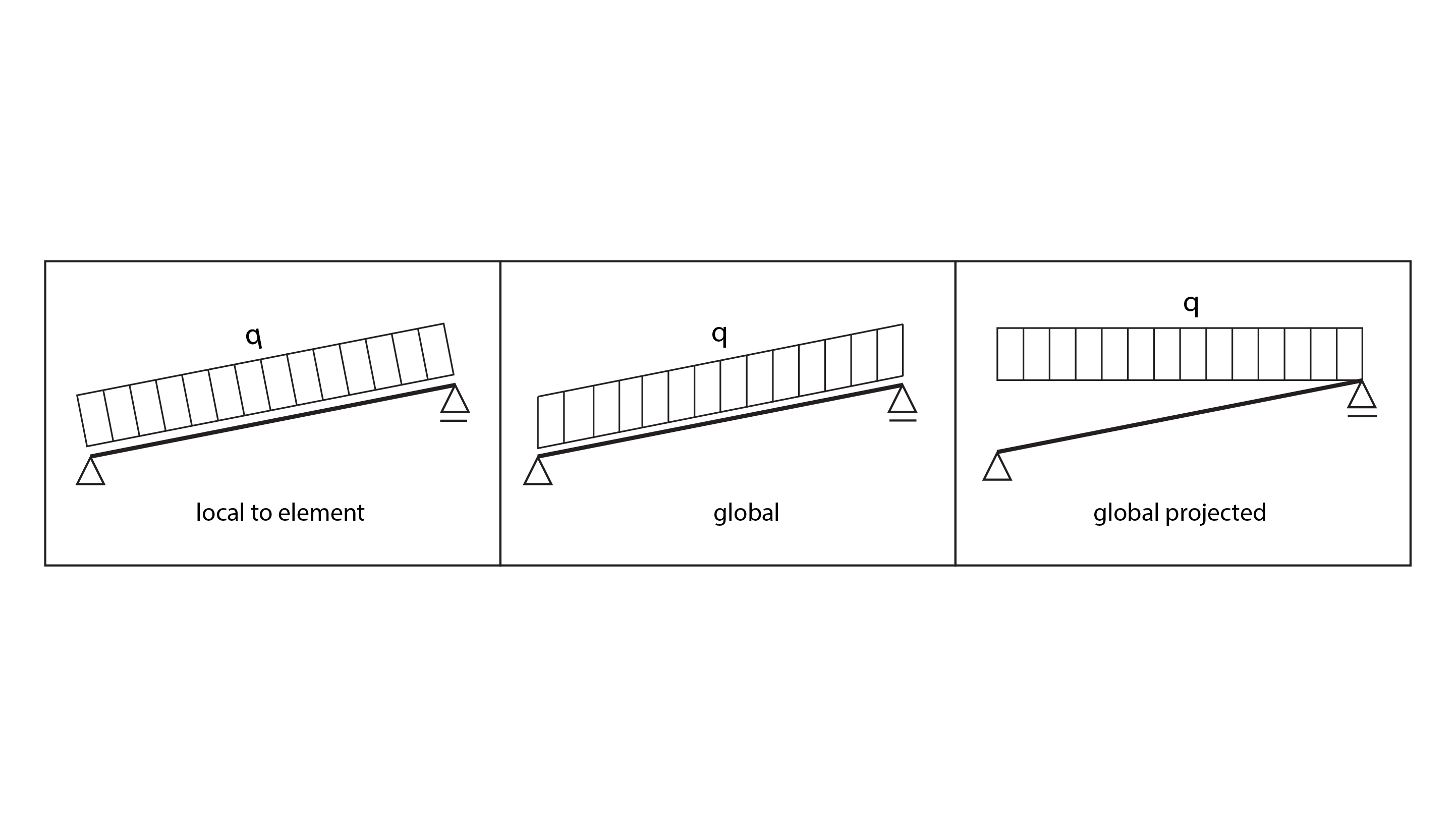
- At the Orientation Option choose Global (the orientation of the load-vector is shown in the image on the right).
- Set the vector of the load by setting -3 value (that represents 1kN/m2 load) to a z vector and connect it to the vector option.
- Specify the Load Case by inputting an integer number to the LCase, in this case it is “LC1”.
Simple Beam Analysis using Karamba3D 6/8
Step 5: Assemble and Analyze the Modellink copied
The Model is an entity that contains all the information related to the structure and it is essential to retrieve the analysis results.
- Use the Assemble Model component through
Make sure you connect all the following entities to the Assembly component.
- Structural elements (beams, mesh shells)
- Supports
- Loads
- Cross Sections
- Materials
- Connect the entities to Assemble Model
The Model Entity from the Assemble component does not yet contain the results from the mechanical response for each load case. That needs to be processed with the Analyze component:
- Connect the Model from the Assemble Model to the Analyse(Karamba3D) component found at
Tip: Grasshopper tends to create data trees which in most cases are unwanted in the Assemble component and will cause errors. Make sure that all the lists of your entities are flattened. Check the following tutorial for more details on data trees in Grasshopper.
Simple Beam Analysis using Karamba3D 7/8
Step 6: View Reslutslink copied
Let’s view the displacement results for beams and shells on the rendered meshes:
- Connect the Analysed Model to the Model View component found at
Beam Results
- Connect the Model from the Model View to the Beam View found at
- Choose in the Render Settings the property that you want to see rendered, in this case it is the Displacement.
- Connect the Legend C (Legend Colores) and the Legend T (Legend Tags) to the Legend component found at
To render the displacement:
- From the Model View open the Display Scales option, choose the Deformation and tweak slider to change the scale of the displacement
Simple Beam Analysis using Karamba3D 8/8
Conclusionlink copied
Congratulations on completing this tutorial! You’ve gained the skills to transform a simple line into a beam, define supports, apply loads, assign materials, and specify cross-sections. Additionally, you’ve learned how to assemble, analyze, and visualize your model. Now, it’s time to put your knowledge into practice—give it a try and start creating!
Useful Tutorials
Useful tutorials below:
Write your feedback.
Write your feedback on "Simple Beam Analysis using Karamba3D"".
If you're providing a specific feedback to a part of the chapter, mention which part (text, image, or video) that you have specific feedback for."Thank your for your feedback.
Your feedback has been submitted successfully and is now awaiting review. We appreciate your input and will ensure it aligns with our guidelines before it’s published.