Rhino Surface Editing
-
Intro
-
Background
-
Creating Surfaces from Curves – 4 options
-
Additional options for generating surfaces from curves
-
Surface Editing Attaching surfaces
-
Surface Editing Detaching surfaces
-
Generating curves on surfaces
-
Extracting curves from surfaces
-
Surface editing options
-
Conclusion
-
Useful Links
Information
| Primary software used | Rhino |
| Course | BKB2WV3 – Digitale Ontwerpomgeving |
| Primary subject | 3D Modelling |
| Secondary subject | 3D modelling |
| Level | Beginner |
| Last updated | November 27, 2024 |
| Keywords |
Responsible
| Teacher | |
| Faculty |
Rhino Surface Editing 0/10
Rhino Surface Editing
In this tutorial you will learn how to generate and edit surfaces based on curves.
If you look at industries like industrial design and the car industry you will see that they often use a different type of geometry which supports the required form freedom neede in the design process. This geometry type is called NURBS. The mathematical description of a NURB is completely different from for example Constructed Solid Geometry. This has its effect on how the geometry can be created and edited.
- Accuracy of the geometry ( important for manufacturing)
- The shapes it can generate
- The ability to adjust the shape
- The workflow of generating the shapes.
Due to its accurate mathematical description of even the most complex shapes it can be used in design and manufacturing.
The form freedom is quite extensive.
There are range of tools available to effectively adjust the geometry and to support formal exploration
Because the geometry is based on curves , the workflow will be completely different then for example the CSG workflow.
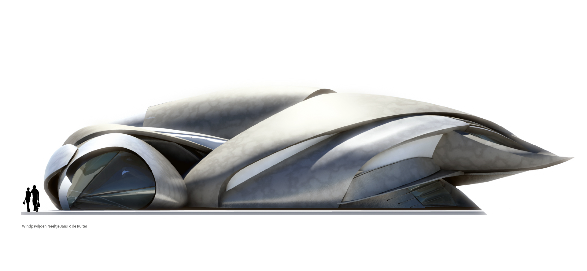
In this workshop we will look at the use and possibilities of NURBS modelling. The method we will use is called curve based modelling. The name already explains its concept. The 3D geometry is made with the help of curves and lines. The process has some similarities with traditional sketch design on paper. The lines defined on paper represent parts of the 3d design. With curve based modelling we use these lines as a basis for making the 3D geometry. This strong link with sketch design can be found in the software used in the car industry and industrial design where with the use of tablets with pen input, designers sketch the design in the computer and convert these lines into curves which can be used for generating the 3d design.
Rhino Surface Editing 1/10
Backgroundlink copied
Isocurves
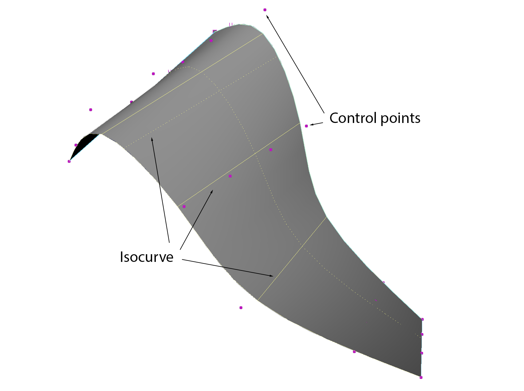
Parts of the geometries topology is comparable with the Bezier curve. The surface supports the same use of weighted vertices to define the curvature and shape of the geometry. The geometry itself can be seen as a combination of two sets of “parallel” curves placed at a crosswise angle, with the mesh defined between the curves. Resulting effect is that the surface can support two different degrees, one in each direction. These curves on the surface are called ISOCURVES. The ISOCURVES will behave almost the same as a Bezier curve. Selecting and moving a vertex on a surface will basically deform the ISOCURVES causing the surface to deform. The more ISOCURVES on a surface, the more vertices are generated to deform the surface OR the higher the degree of the curves, the more vertices will be generated per ISOCURVES and surface as a whole.
The NURBS surface contains several different components. We have already found out that the NURBS surface contains ISOCURVES. The ISOCURVES are the sets of crosswise angled curves on the surface. They are in fact the curves where the surface is based on but are part of the surface itself.
Rhino Curve based modelling
With Rhino it is possible to create surfaces based on curves. These curves are created directly by line elements like polylines, arcs etc., or indirectly by extracting line elements from early created surfaces.
Modeling in rhino environment starts with curves and mostly ends with curves. This means that almost everything made in Rhino environment could be easily developed to be constructable. There are special curve editing tools available in Rhino that help designers to easily manipulate curves, specially various kinds of splines. Using these controllable splines one can easily build NURBS objects (NURBS stands for Non Uniform Rational B-Splines: Those objects that usually called free-forms by Architects!).
The workflow of curve based modelling is quite straight forward.
- You create a set of curves
- With the help of the curves you make surfaces
- These surfaces you can adjust by directly editing the surface or adjusting the curves the geometry was made from.
Rhino Surface Editing 2/10
Creating Surfaces from Curves – 4 optionslink copied
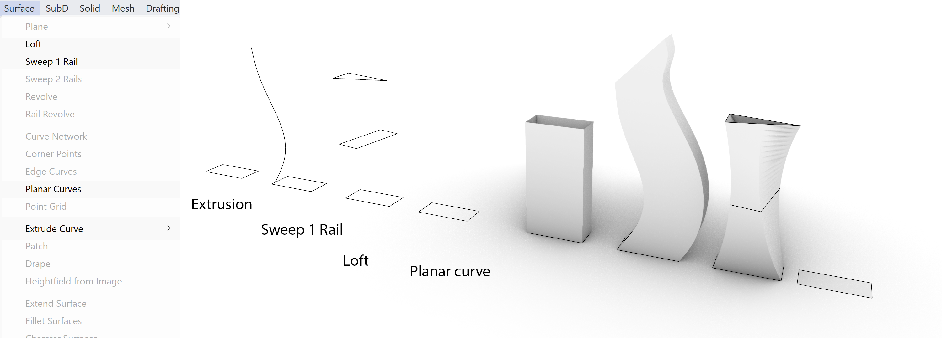
Once you have the curves you can start generating the surfaces. Although you can make almost any kind of shape and create extremely complex designs the technique of generating this complexity is quite simple. This has to do with the fact that there are no more than 4 main techniques of generating shapes from curves. If you know these four techniques you can build almost anything.
- The first option is the extrusion of a curve. This can be a closed curve like the example or an open curve. The form freedom which you have with this option is limited to the shape of the curve and the height of the extrusion.
- The sweep 1 rail increase the form freedom because the direction of the extrusion can be varied. This gives you more possibilities to alter the final outcome of the shape than the straight extrusion. The shape can have different sections.
- The loft is in this set one of the most powerful modelling options. You not only can change the section over the height of the shape but also the location of the sections. This option can generate very simple complex shapes.
- The last option is the simplest. It will generate a surface on the inside of a closed flat curve.
Although there are additional options available for generating surfaces, they are all related to these 4 principle options. All commands to create surfaces can be found under Surface.
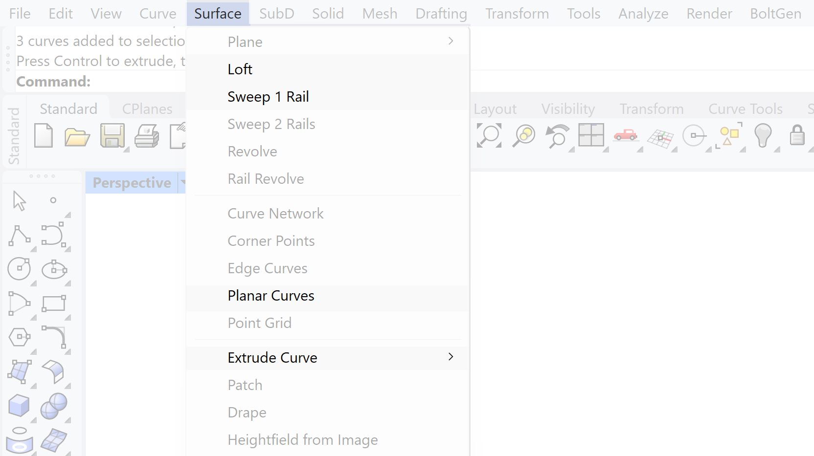
Extrude Curve
Extrude Curve creates an extrusion of a curve profile.
There are several options available which gives you a bit more choice in complexity of the generated geometry. The option of extruding along a curve differs from the Sweep 1 rail because the section does not align with the curve generating a non-continuous section. There are four ways in Rhino to create an extrusion:
- Straight
- Along Curve
- To Point
- Tapered
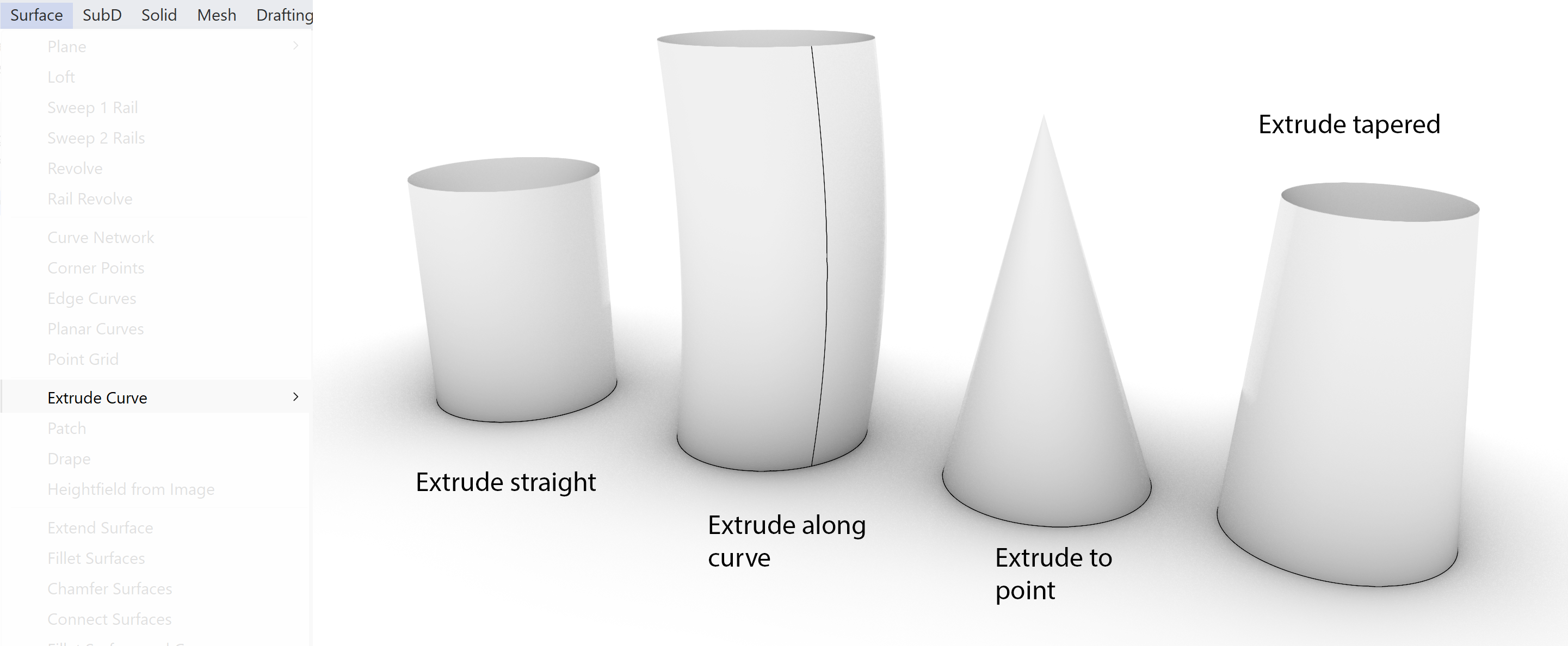
Once the extrusion is generated with the Record History option on, the surface can be adjusted by adjusting the curve profile. There is a parametric relation between the Profile and the resulting Surface.

Sweep 1 Rail
The Sweep 1 Rail creates a surface by sweeping at least one profile curve along a rail.
This option is a more complex version of the extrude option. With the Sweep option we also have control over the direction of the sweep. This can be a straight line or a curve. Another difference is the option of using more then 1 profile. This gives additional control in the generation of the surface and its possibility to be later altered, due the parametric relationship of the curves and surface.

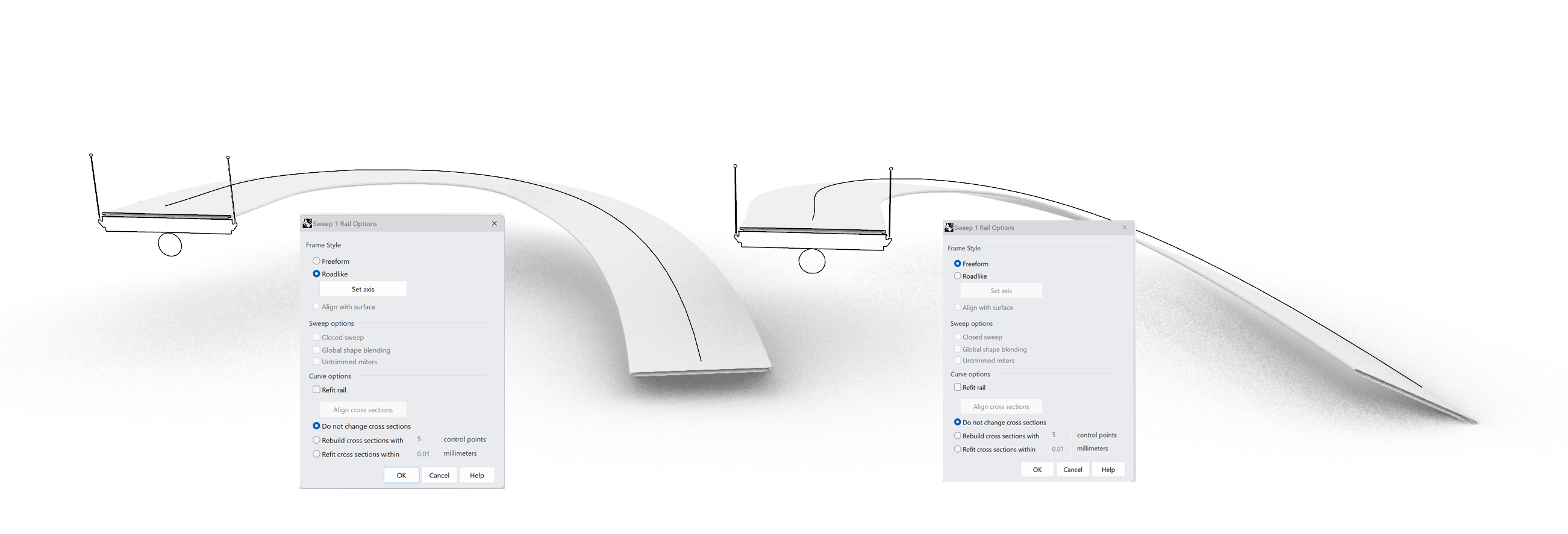
When the sweep is created it opens a menu with some options. The Road like option is used to prevent tilting of your profile during the sweep keeping the profile, for example of a road deck, horizontal.
Loft
A loft creates a surface between two or more selected curves.
Make sure you select the curves one by one, in the right order, then the lofted surface will follow the selected order.

It is important to align the arrows when the loft is created. It indicates in which direction the surface is made. Also make sure the line between the arrows is at an approximate same height at all the shapes. This line will be the edge of the surface. The way how the surface is generated between the curves can be adjusted using the Loft options menu. Altering one of the curves will adjust the generated surface due its parametric setup.

Planar Curve
Planar Curve creates a planar surface from a planar curves.
Curves are allowed to overlap but should always be closed to define the edge of the surface. As the command says it doesn’t support curves which are not in the same plane.

Rhino Surface Editing 3/10
Additional options for generating surfaces from curveslink copied
Curve Network
Curve Network is ideal for sketching the contours of your design and convert the lines and curves into a set of surfaces.
This option needs 4 curves which will form the sides of the surface. The advantage is that the curves don’t have to be in the same plane and can be continuous adding to its capability to create complex shapes. It is often used in a network of curves creating a series of patches describing the shape. This technique is for example also used in car design, where the complex surfaces of a car body are built from a set of patches or curved networks. That is why it is called patch modelling.

Sweep 2 Rail
Sweep 2 rail creates a surface defined by two curves (rails) and at least 1 profile between the rails
This option is in essence similar to the sweep 1 rail , the difference is that here we use two rails. The profile will be scaled and stretched to accommodate the connection between the two rails. Because of the 2 rails the sides of the Sweep are accurately defined.

Revolve
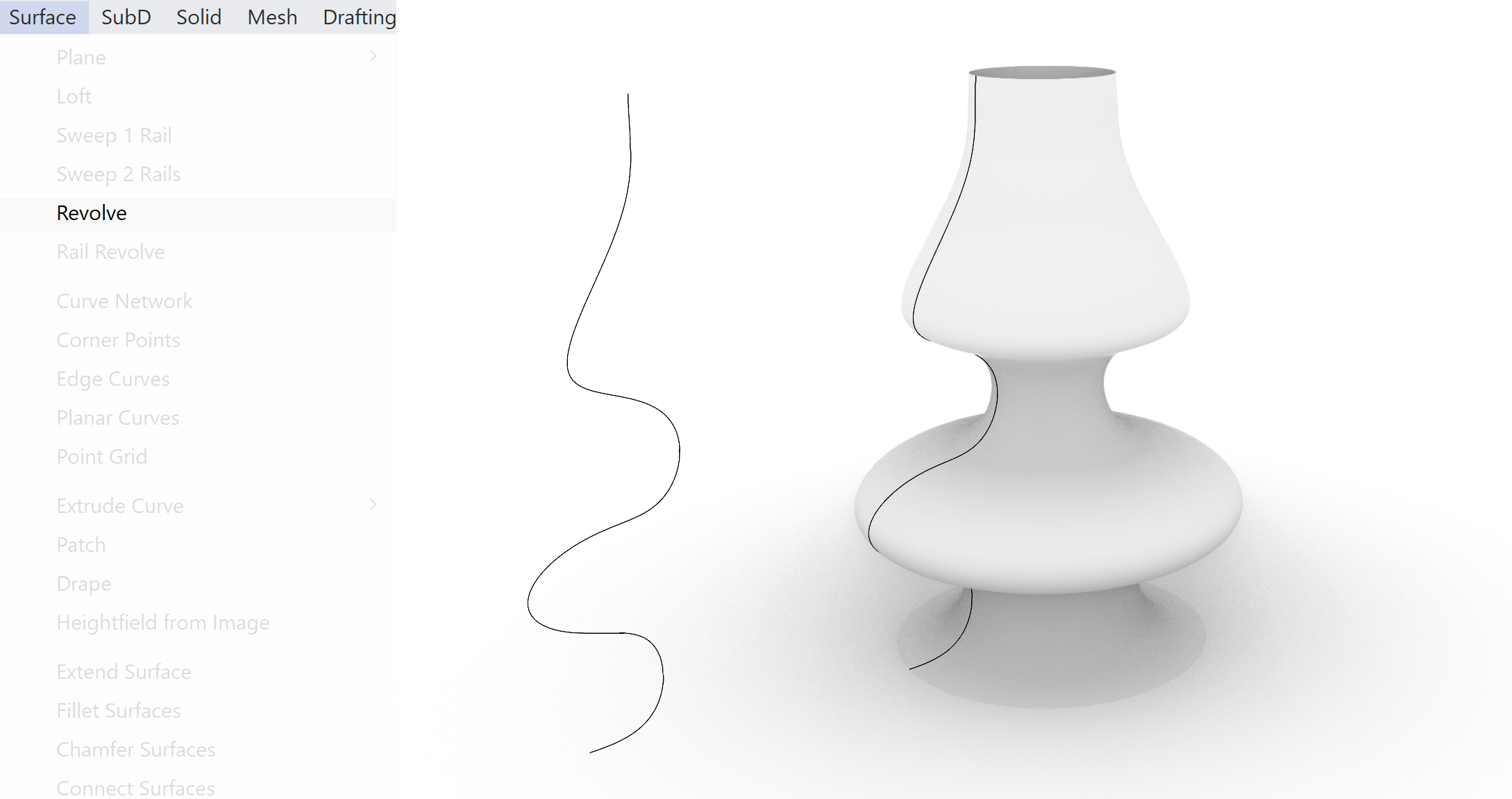
Revolving a curve allows the generation of rotational symmetric surfaces. If the profile curve of the revolved surface is changed the surface will change accordingly.
Rail Revolve
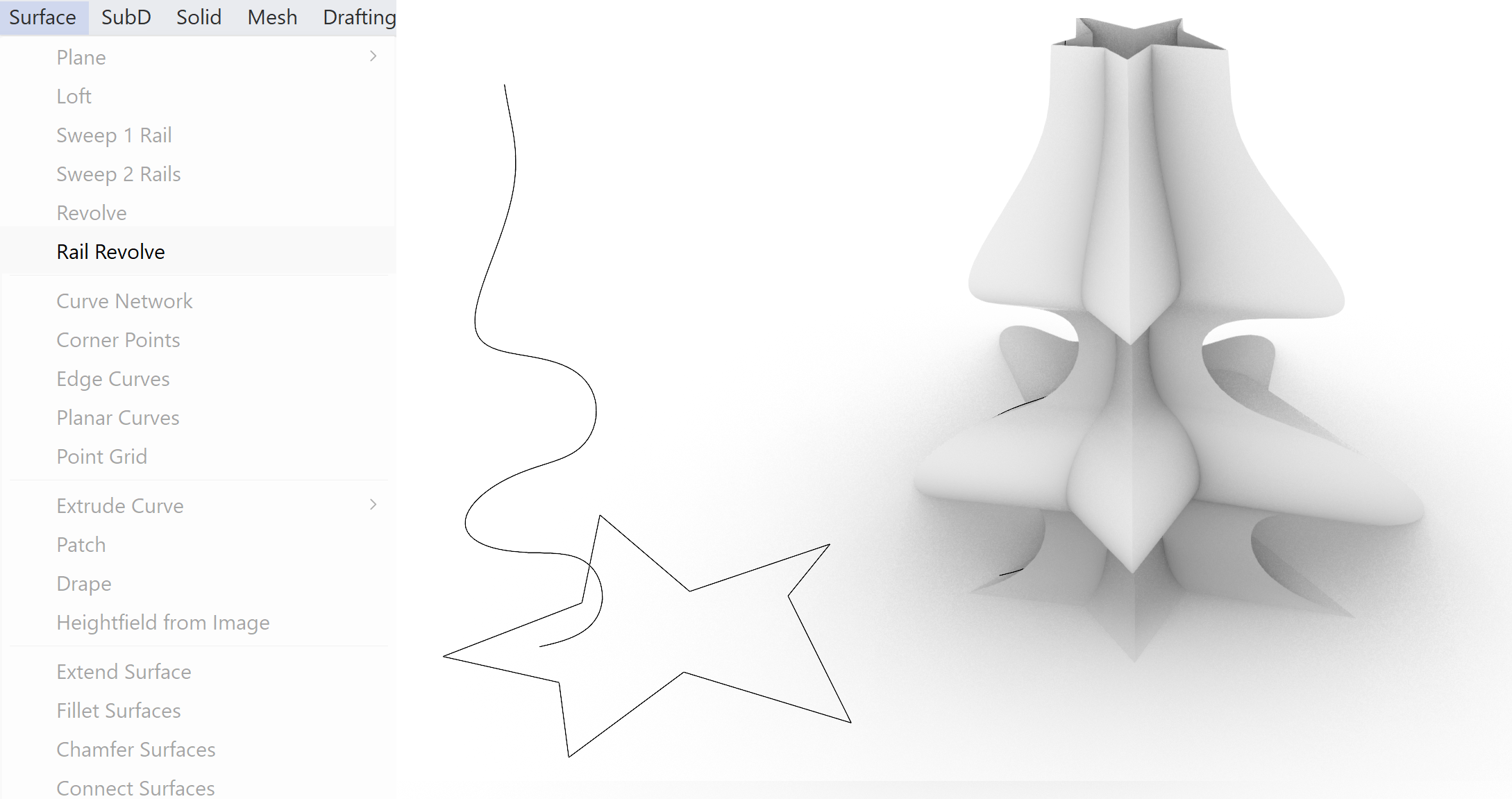
Rail Revolve is a derivative of the simpler revolve option. It creates a surface by revolving a profile curve around an axis, but the surface edge is defined by an extra curve (rail).
Rhino Surface Editing 4/10
Surface Editing Attaching surfaceslink copied
The options of editing surfaces are remarkedly similar to the editing options of curves. This is a result of its mathematical description of the curves and surfaces. The principle use of Control Points in curves as well as surfaces to define its curvature impacts the edit options, where the curve the 1 dimensional version is and the surface the 2 dimensional version.
Join
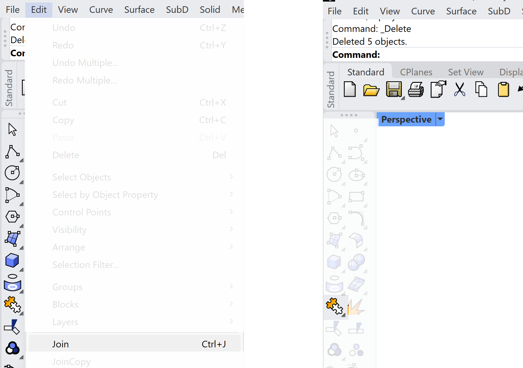
Like the curves surfaces can be combined into a single surface by joining them. If the surfaces connect at the edges they can be combined into a single object. If the surfaces together form a closed object the separate surfaces are converted to a single Closed Poly(many) Surface. This Closed Polysurface will have the same properties as a Solid. That means also the same edit options as a solid. You can use the Join icon on the toolbar.

Match
Match is a more advanced method of joining surfaces
This will potentially align the surfaces into a smooth edge. The smoothness is dictated by the selected continuity of the joining surfaces. This allows for a segmented surface which still will be completely smooth. The separate patches are aligned at the edges so the whole surface can be completely smooth.
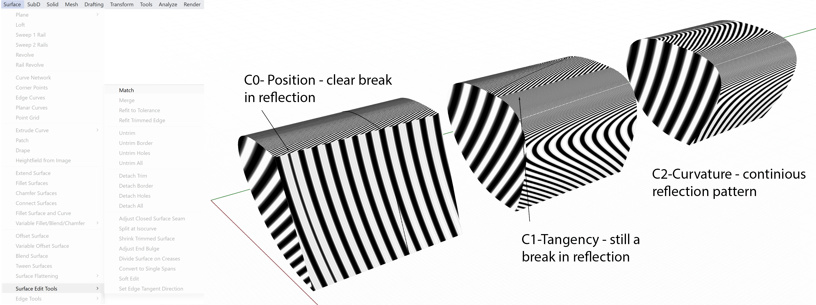
To analyze the continuity of the edge connection we can use a zebra analysis. This will generate a reflection pattern on the surface. The distortion and continuity of the reflected pattern will inform about the continuity of the connected surfaces.
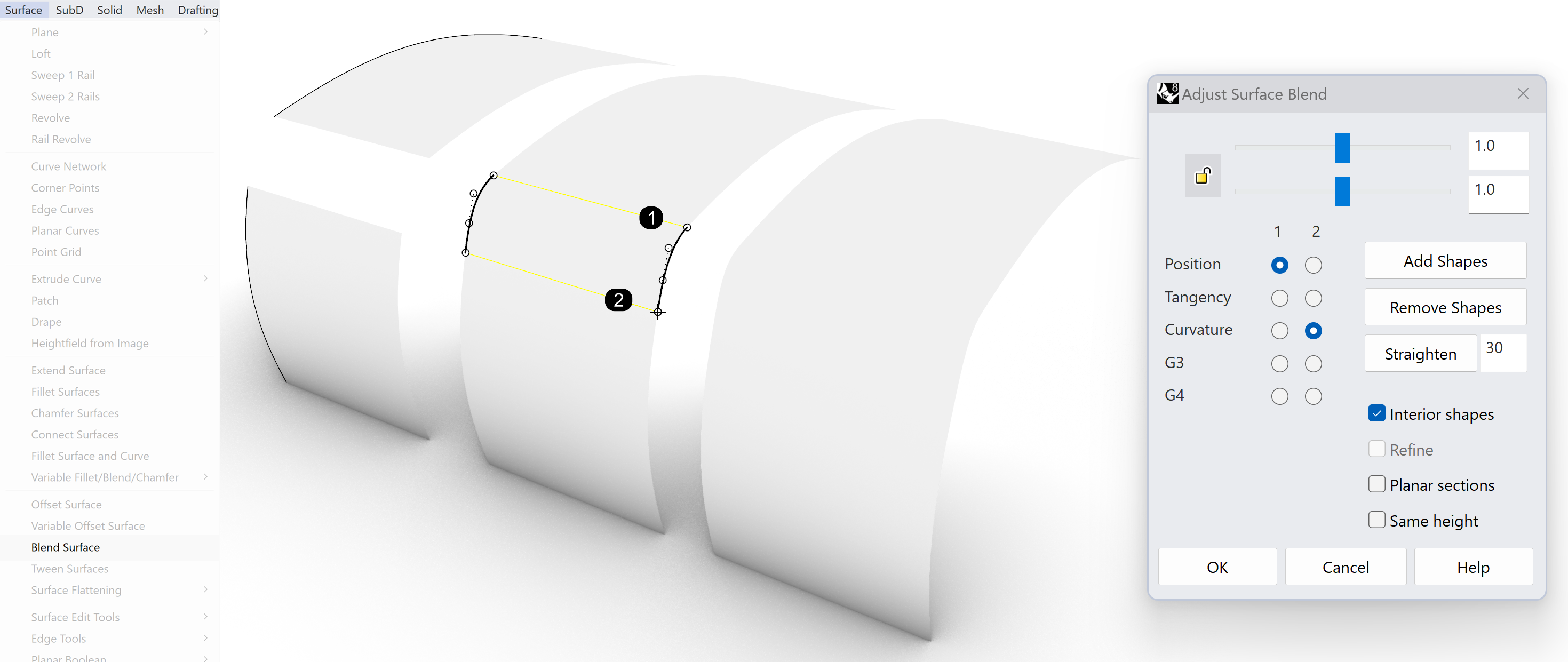
There are 3 options available
- Position – a hard connect, the surfaces don’t change
- Tangency – surfaces blended together based on the alignment of the tangency of both surface edges
- Curvature – complete smooth transition between the surfaces. The edge and surface ends will be merged into a curvature description.

Blend surface
Blend Surface makes a smooth connection between the two surfaces
You can adjust the curvature or bulge by changing the two sliders at the top. How the surface will react on the sliders depend on the chosen continuity (Position, Tangency, Curvature) You can see a preview via the dialog box and do adjustments.
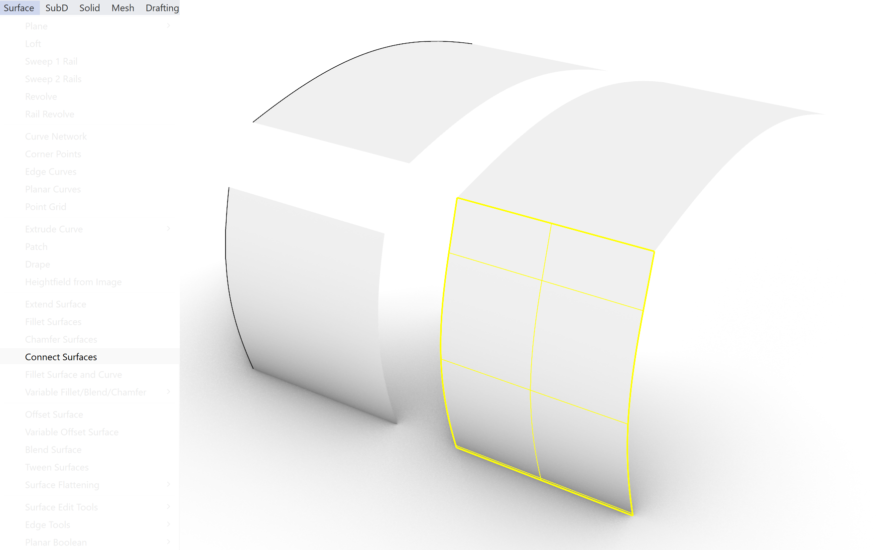
Connect surface
Rhino Surface Editing 5/10
Surface Editing Detaching surfaceslink copied
If you want to cut a curve in separate parts you will have to define the point where the curve has to be cut. This can be done by defining a point on the curve or one could use a cutting line. However, defining a point on a surface is useless if it has to be cut. However, a line can also be used as a cutting line on a surface. The line should define a closed area on the surface or a segment on the surface. Once the curve is defined you can use the Split or Trim function to cut out a part of the surface.
Trim and Split
If you want to cut a curve in separate parts you will have to define the point where the curve has to be cut. This can be done by defining a point on the curve or one could use a cutting line. However, defining a point on a surface is useless if it has to be cut. However, a line can also be used as a cutting line on a surface. The line should define a closed area on the surface or a segment on the surface. Once the curve is defined you can use the Split or Trim function to cut out a part of the surface.

Trim removes selected parts of your surface.
Split is almost the same as trim, but does not remove any geometry.
To undo the trim operation on a surface. First explode the surface to generate single surfaces!
This option is similar to the Trim and Split option for curves. With both options a cutting line might suffice, with a surface Split or Trim it might be necessary to use a surface as a cutting surface.
Exploding a surface
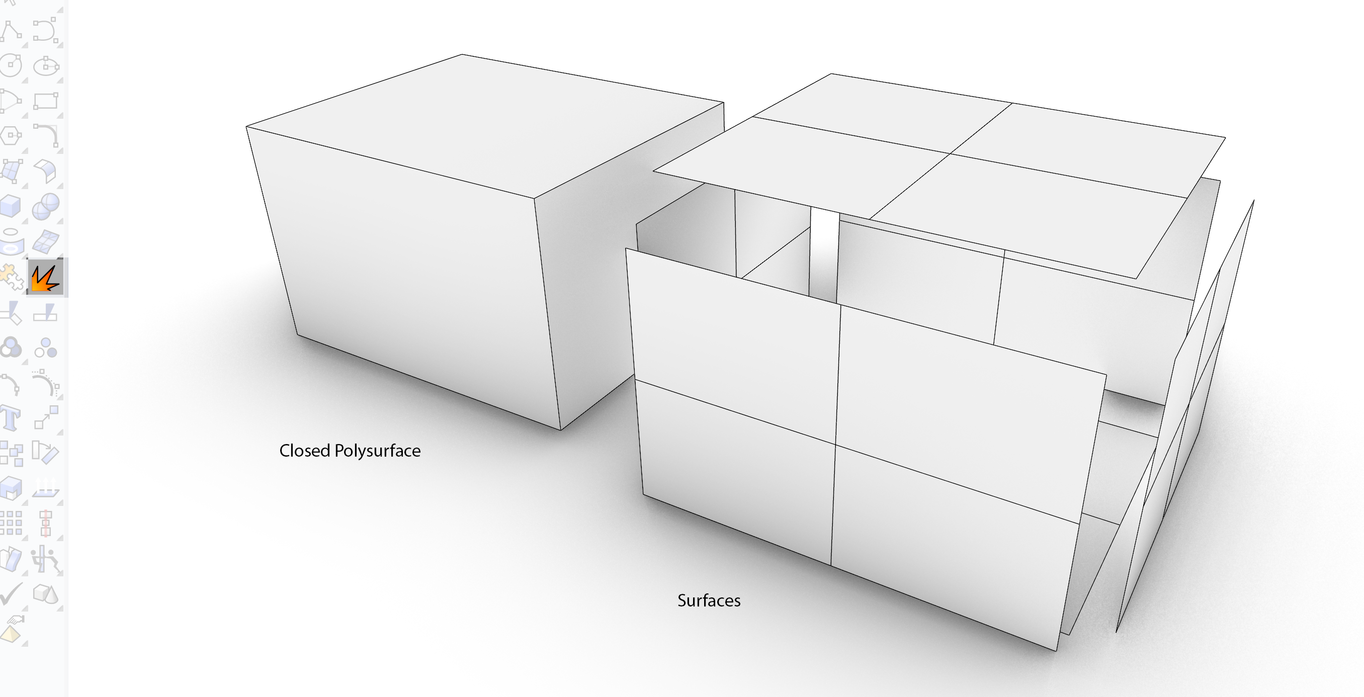
If you have a Closed Polysurface it will behave like a Solid. This might be problematic if you want to use the surface edit options on the Closed Polysurface. To convert the Solid into a set of surfaces you can Explode it. This will delete the description of how the surfaces are connected needed for the Solid behavior and transforms the single object into a set of separate unrelated surfaces. These surfaces can be edited with the surface edit options. If you have a polysurface which isn’t closed, you might want to extract one of the surfaces to replace or delete. In this case you can use the explode options also as it will deconstruct the Polysurface into separate single surfaces.
Rhino Surface Editing 6/10
Generating curves on surfaceslink copied
One of the basic principles of Curve Based Modeling is that the surfaces are generated from a curve or a set of curves. The possibility to generate curves on a surface is part of this functionality. These curves then can be the basis for generating addition surfaces, cutting lines for a trim or split or for example a rail for a Sweep 1 Rail option.
Intersection

Project curve on surface
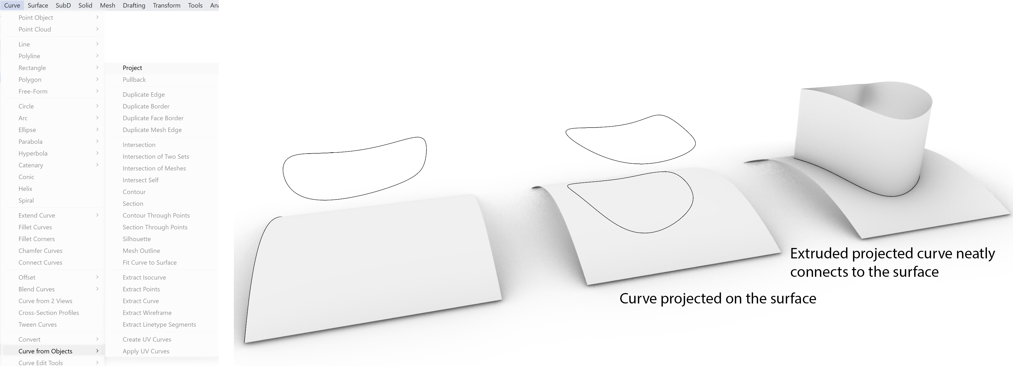
Pullback
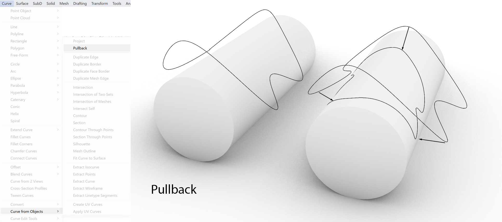
To resolve the problem of the behaviour of the curve when projected onto an edge of the surface the Pullback option is available.
This option makes it possible to 3 dimensionally define a curve around a surface and let it be pulled onto the surface along the surface normal.
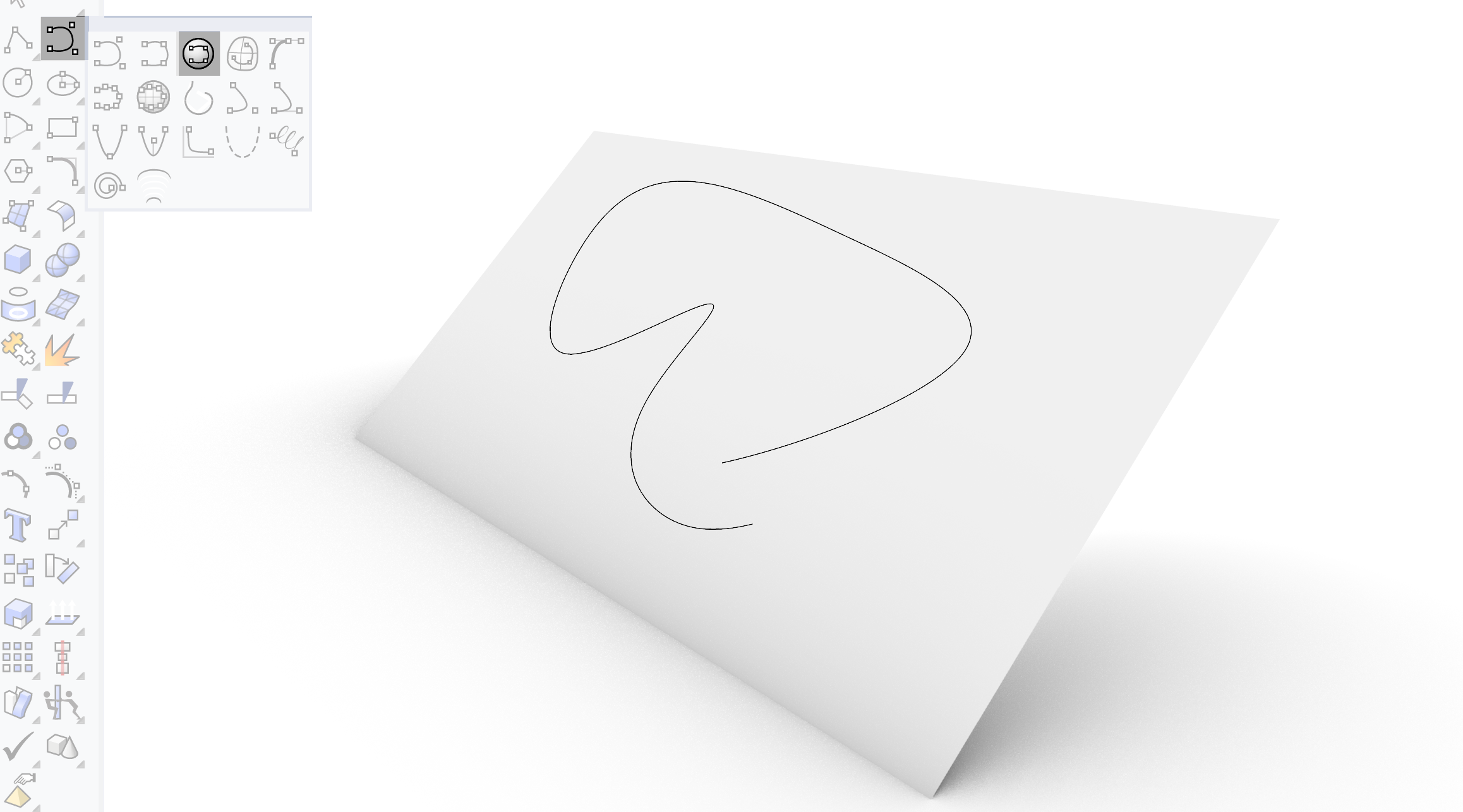
Drawing directly on a surface
“Interpolate On Surface” enables direct drawing on a surface.
If the curve is moved it will not remain connected to the surface. This is a limitation. The advantage though is there is no dependance on projection direction or unwanted Pullback results.
Rhino Surface Editing 7/10
Extracting curves from surfaceslink copied
One of the key functionalities of curve-based modelling is the possibility to extract curves from surfaces and reuse them as a basis for new geometry. This option makes it possible to keep building on existing surfaces, thereby enhancing the complexity and accuracy of the representation of the design.

There are various options to create curves from objects.
Go in your menu:
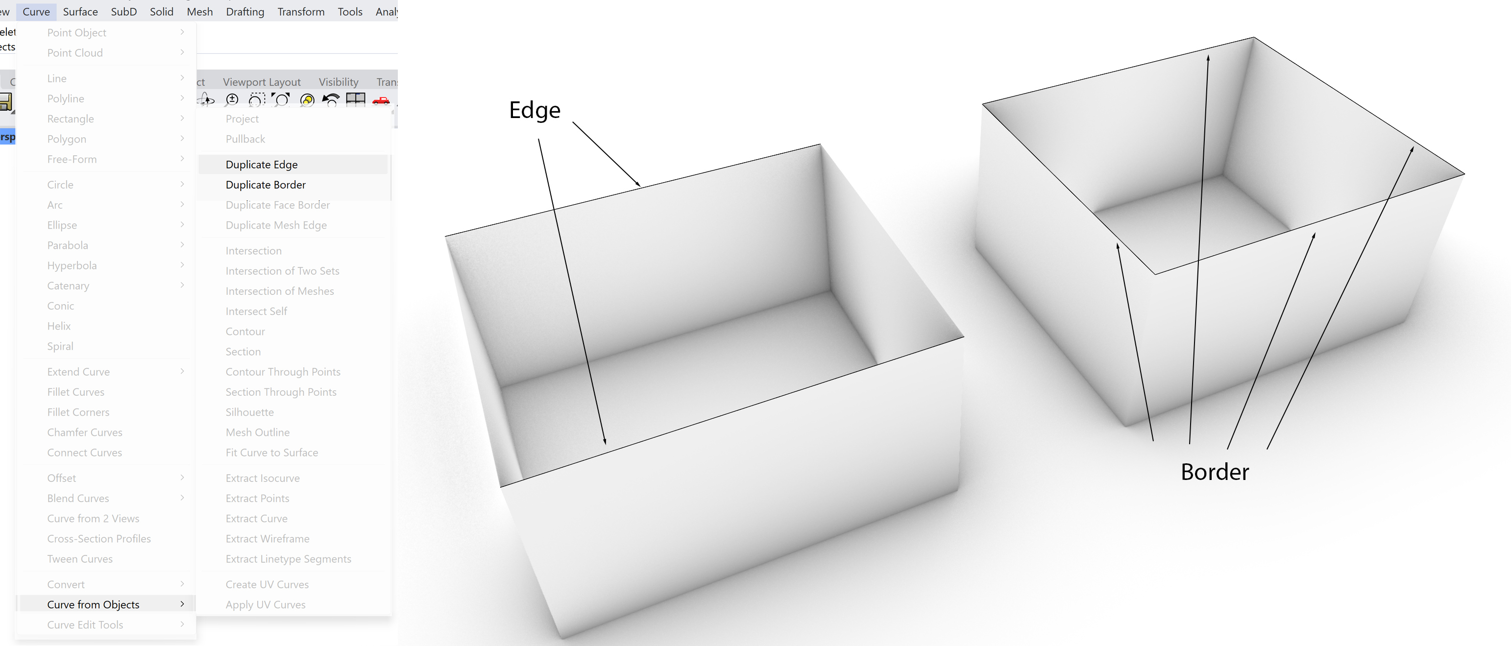
Duplicate Edge or Border
The edge of the surface can be selected. The edge for example can be used to build additional geometry.
The whole border of the surface can also be selected. This option can be useful to cap an object or use the curve to create the edge of the object in 3D.
Both options copy the edges of the geometry of the surface and are often used to form a basis for capping the geometry. The difference is that the Duplicate Edge option gives you the possibility to select the edges by hand. Not only the open edges but also the side edges of the geometry. Duplicate border will select automatically only the open edges of the geometry.
Extract Isocurve
In contrast to the Duplicate option, the extraction of a curve depends on the definition of the shape by its isocurve. The option of extraction will enable you to extract curves from the surface.
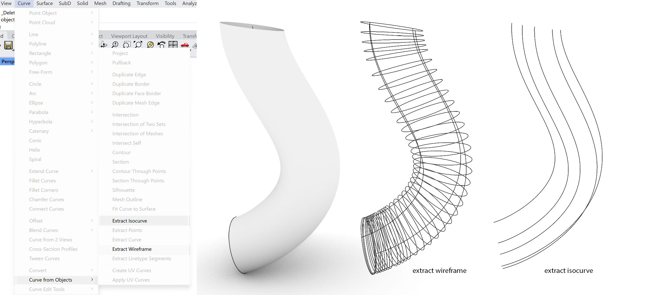
This option makes it possible to extract an isocurves from the surface. Please check the command line to toggle between the u or v direction of the isocurves. The isocurves can be then used as a basis for new geometry or as a cutting line on the geometry.
The wireframe are the visible isocurves on the surface. When the command is executed all the isocurves and edges will be extracted and converted into curves. With these curves the surface can be rebuild or adjusted by adjusting first the curves and then rebuild the surface.
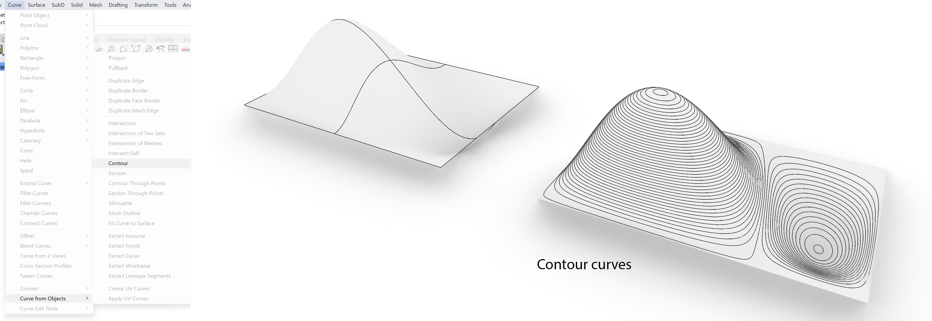
Contour
The contour option is a powerful tool to generate a series of sections through the geometry. This option is often used to “layer” a complex shape into series of flat surfaces.
Rhino Surface Editing 8/10
Surface editing optionslink copied
Additional edit options are similar to the options for the curves. This reason for this is actually quite simple. A NURBS 2D surface is , to place it simply, a 2D derivative of the 1D curve. Most of the mathematics behind the curve are similar to the surface. The result is that a whole range of curve tools are also applicable to the surface, taking in account that it has an extra dimension.
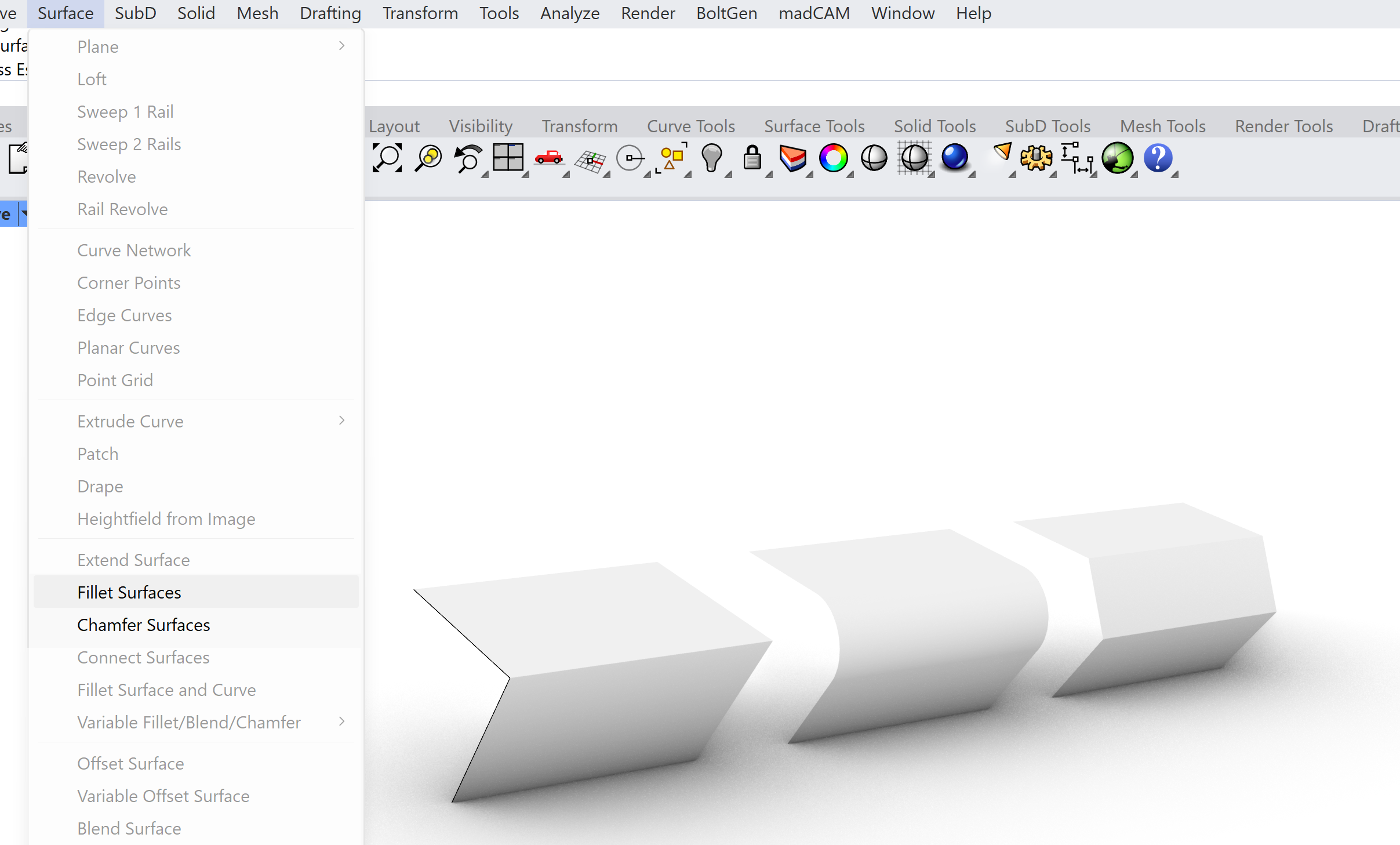
Several options for extending a surface:
Fillet Surfaces – make a fillet between two surfaces (rounding of the edge):
Chamfer Surfaces – makes a bevel(straight edge) between two surfaces:
Variable Fillet Surfaces – as above but with more options:
Variable Blend Surfaces is similar with Variable Fillet Surfaces, but has more control points:
You can offset a surface in the direction of the normals of the surface. An option to generate thickness to a surface. Check the command line for options. The Solid yes or no will dictate if the surfaces will be closed at the edges.
Rhino Surface Editing 9/10
Conclusionlink copied
This approach of using curves as a basis for generating surfaces allows you to generate simple as well as very complex geometry which can easily adjusted by altering the curves which the geometry is made from. This makes it a powerful tool in design, not limiting the complexity of forms which can be created and in the iterative design process be adapted.
Rhino Surface Editing 10/10
Useful Linkslink copied
Write your feedback.
Write your feedback on "Rhino Surface Editing"".
If you're providing a specific feedback to a part of the chapter, mention which part (text, image, or video) that you have specific feedback for."Thank your for your feedback.
Your feedback has been submitted successfully and is now awaiting review. We appreciate your input and will ensure it aligns with our guidelines before it’s published.
