Modeling an orthogonal pavillion in Houdini
-
Intro
-
The Grid: Beams and Columns
-
The Grid: Overall Structure
-
The Exposition Room
-
Adding Walls
-
Adding Roof and Stairs
-
The Pavillion
Information
| Primary software used | Houdini |
| Software version | 1.0 |
| Course | Modeling an orthogonal pavillion in Houdini |
| Primary subject | Parametric Modeling |
| Secondary subject | 3D modelling |
| Level | Beginner |
| Last updated | February 12, 2025 |
| Keywords |
Responsible
| Teacher | |
| Faculty |
Modeling an orthogonal pavillion in Houdini 0/6
Modeling an orthogonal pavillion in Houdini
In this tutorial you will learn the basic tools and workflow for modelling in Houdini.
Before starting the tutorial you will have read page 1 to 17 from the Houdni Foundations book which you can find here. Having followed the first workshop will defenitely help as well.
The Houdini Shortcut Cheat Sheet might be helpful, you can find it here.
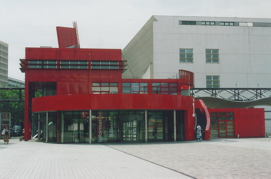
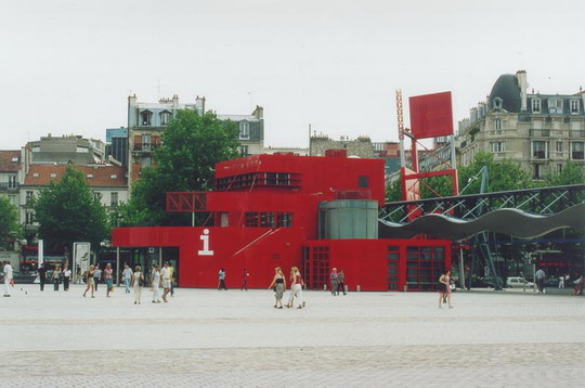
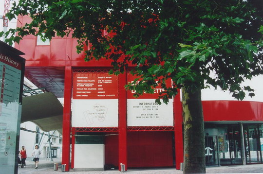
The building we will create in this tutorials is one of the follies of Parc de la Villette in Paris.
Modeling an orthogonal pavillion in Houdini 1/6
The Grid: Beams and Columnslink copied
We will start with modelling the basic structure of the pavillion.
This folly has a cube of 10.8m x 10.8m x 10.8m as base and consists of smaller cubes of 3.6m x 3.6m x 3.6m. It is build up out of columns filled with square facade elements.
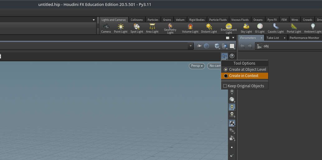
Before starting to model, make one adjustment to the default interface of Houdini. In the top right corner of the viewer pane, click on the icon with the three spheres on a plane and select Create in Context.
You can make this the default setting if you want to by going to Edit > Preferences > Objects and Geometry > Default Context Creation.
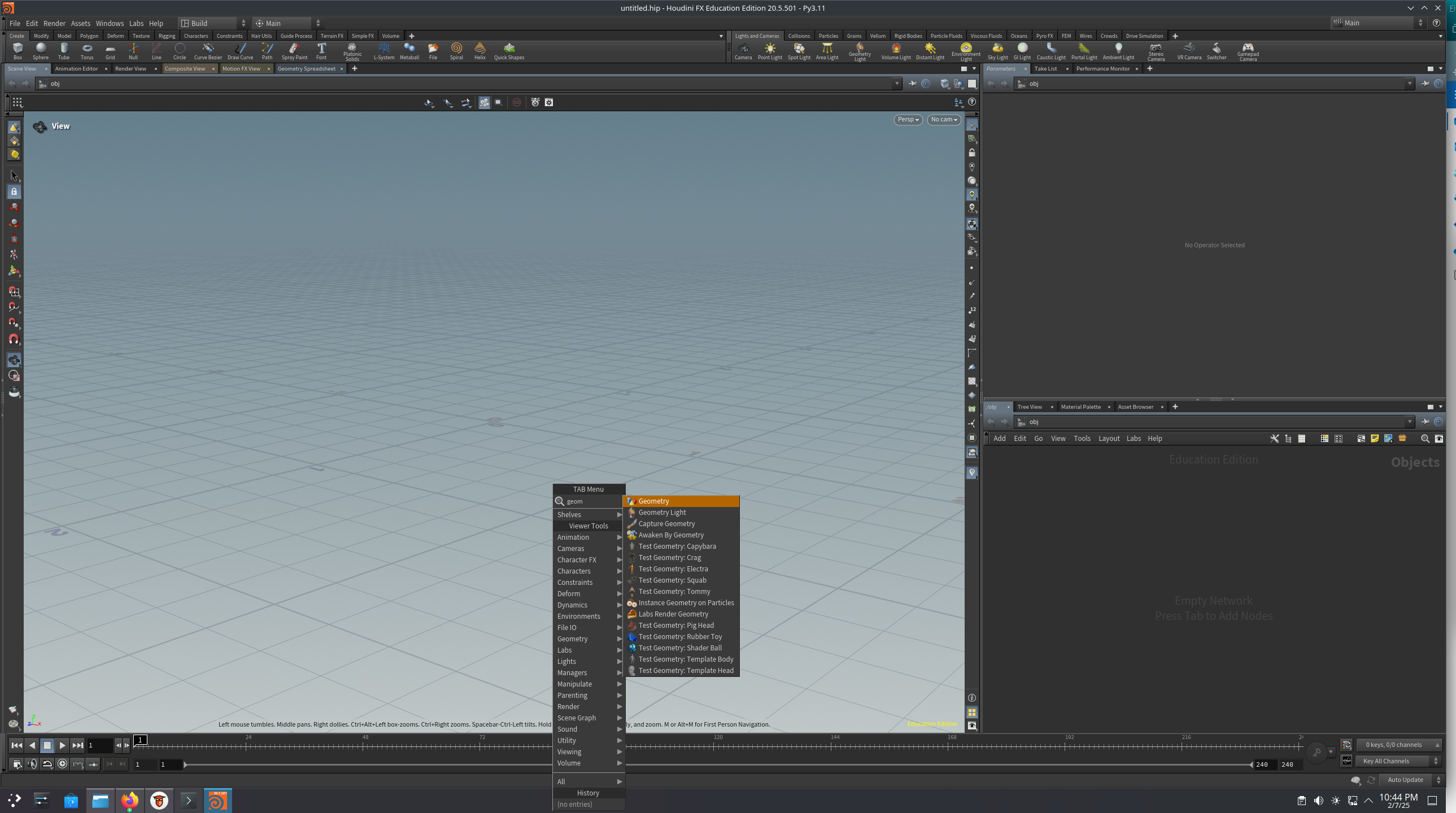
We will start with creating the shape of a column. Basically, a column is a box and can be made with one of Houdini’s basic shapes: the box. As Houdini is a lit bit different then other 3D modellers, we need to place a container to hold our geometry. Press the TAB key in the viewer or network pane and then start typing geometry. A node called geo1 is placed in the network pane.
There is a small difference between using the tab menu in the viewer pane and in the network pane. In the network pane the node is placed automatically in the network pane while in the network pane, you need to press enter or click the LMB to place the node.
Double click on the geo1 node or select the node and press u to “dive inside”. Press the tab menu again and now start typing box. A node called box1 is now placed in the geo1 container.
See the page Tab menu for more information.
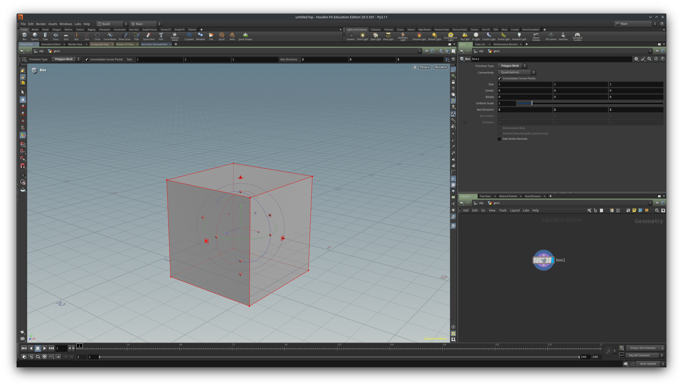
In the view pane you can use the handles to change the size of the box. Move the little squares on the red arrows with the LMB to change the shape. Try to set the size close to 0.3 in x, 3.6 in y and 0.3 in z. Drag the green arrow up to place the box on the grid (by default the center of geometry is on the origin of the grid).
For more information on handles see Using handles
Of course you can type the values in the parameter pane so make sure it the size parameter is set to 03, 3.6, 0.3 and the center parameter to 0, 1.8, 0.
Place two more boxes, these will become the beams. Use the following values for the parameters:
| sizex | sizey | sizez | centerx | centery | centerz | |
| column | 0.3 | 3.6 | 0.3 | 0 | 1.8 | 0 |
| beam in x | 3.3 | 0.3 | 0.3 | 1.8 | 3.45 | 0 |
| beam in z | 0.3 | 0.3 | 3.3 | 0 | 3.45 | -1.8 |
We have now three seperate boxes in our geo1 network but you can only see and “operate” on one of them at the time. By merging the nodes, they become one single geometry. Press tab again and type merge. Lay down the merge node in the network and then select all three boxes. Left click on the little dot at the bottom of one of the nodes and a wire will attach to your mouse cursor. Drag the three wires to the top of the curved bar on the merge node and click on it. Now your boxes are connected on the merge node.
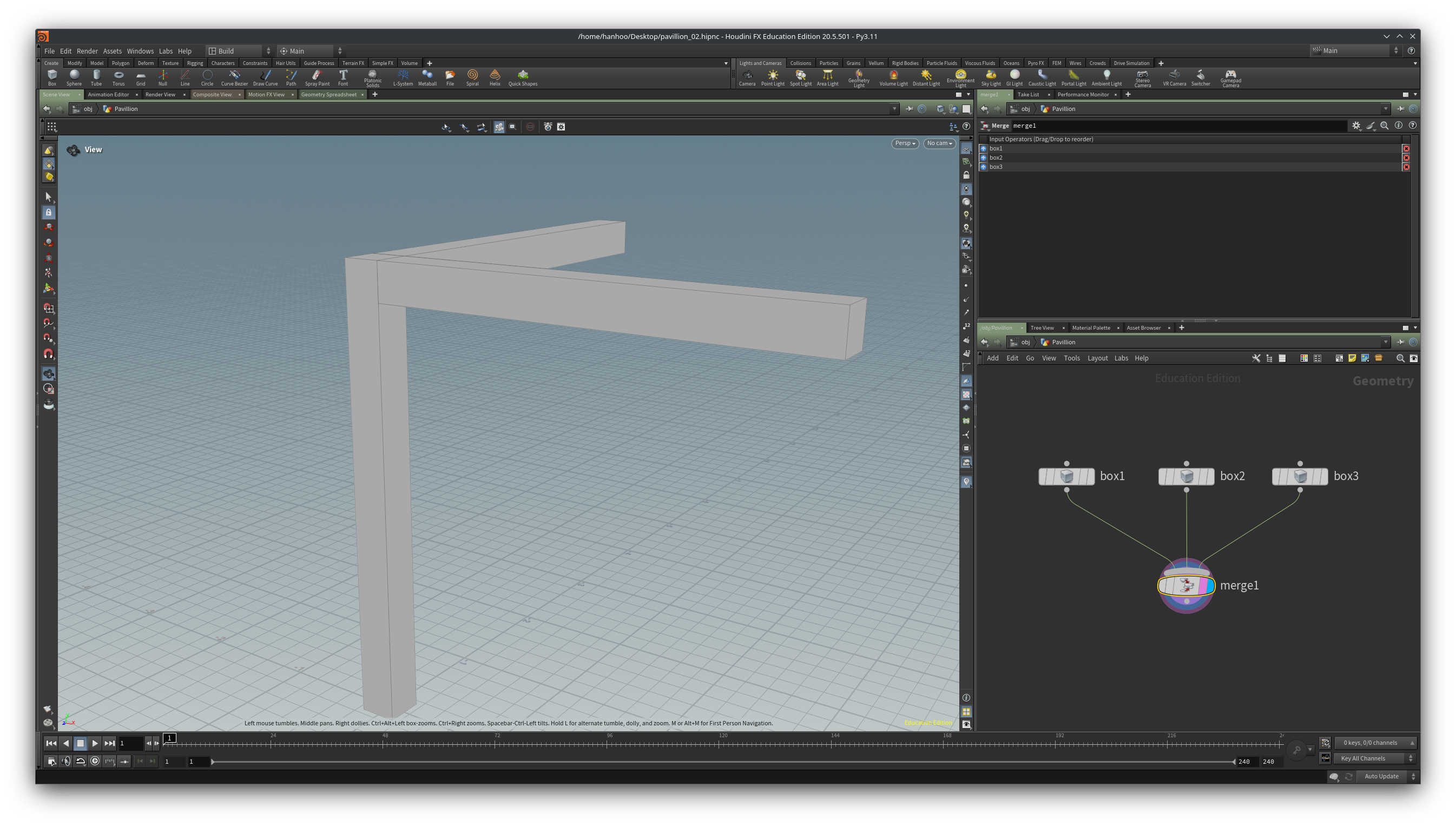
We made our first little network. Now is a good time to save your file. Give it a proper name, e.g. AR0916_intro_pavillion. Our network is going to grow quite a bit before we will have a proper pavillion.
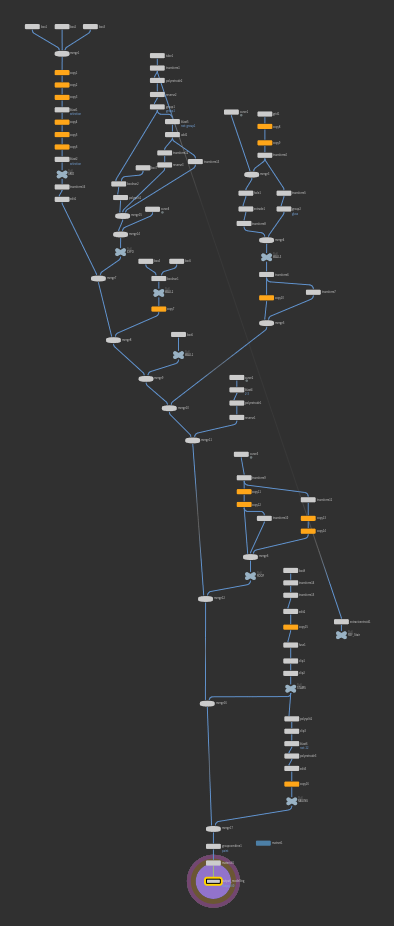
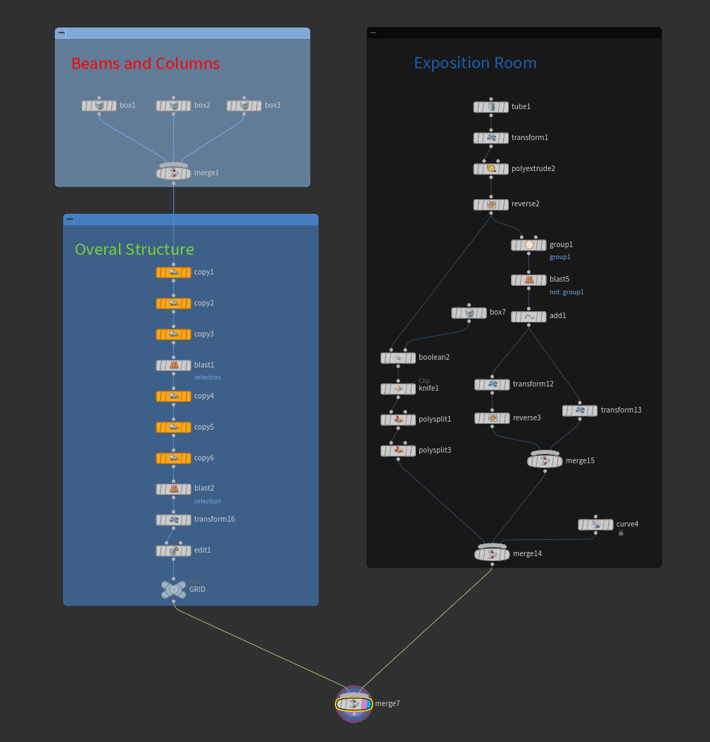
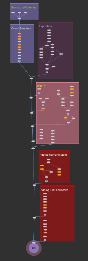
Below you can see an overview of the network as it might look at the end of the tutorial. We wil continue in the next chapter with modelling the structure of the pavillion.
Modeling an orthogonal pavillion in Houdini 2/6
The Grid: Overall Structurelink copied
We have our beam and column, now we are going to build the main structure of the pavillion. This entails copying the beams around using the Duplicate node and deleting some geometry using the Blast node.
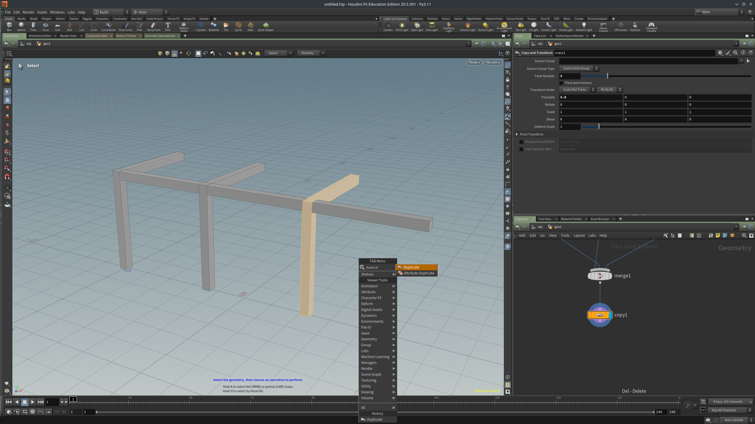
Press tab and then type duplicate (tab -> duplicate). Lay down the node and wire in the merge1 node. Set the Total number parameter to 3 and the Translate parameter to 3.6, 0, 0. We have now three columns and 6 beams. In the view pane press the s key to switch to select mode, press 4 to select geometry. Double click on the last column and the last beam pointing in the z-direction, the selected geometry will turn yellowish. With the selected geometry tab->duplicate. A new Copy and Transform node will be placed after the copy1 node. In the Source Group paramater you can see that only primitive numbers 36-47 are selected. Set the Translate parameter to 3.6, 0, 0. We have now our final column and beam.
For a more thorough explanation on selecting geometry in Houdni see Selecting objects and components
Remember that Houdini is a non destrcutive modeller so you can always change parameters, rewire nodes etc when you made a mistake, just don’t panic!
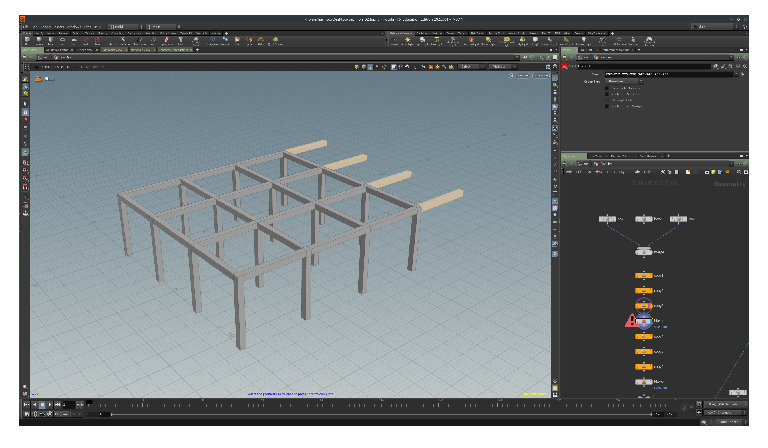
We made a duplication in the x-direction, so the logical next step is to copy in the z-direction. Add another duplicate node, tab->duplicate, and set the Total Number to 4 and Translate to 0, 0, 3.6. We got some beams sticking out so we are going to delete these. There is a Delete node but we are going to use the Blast node because it sounds way more fun. In the view pane, press s again to go into select mode and select all the beams sticking out by double clicking on each of them.
Now the last step for the big cube of the pavilion, copying all teh beams and columns up. Add another duplicate node and set Total Number to 3 and Translate to 0, 3.6, 0.
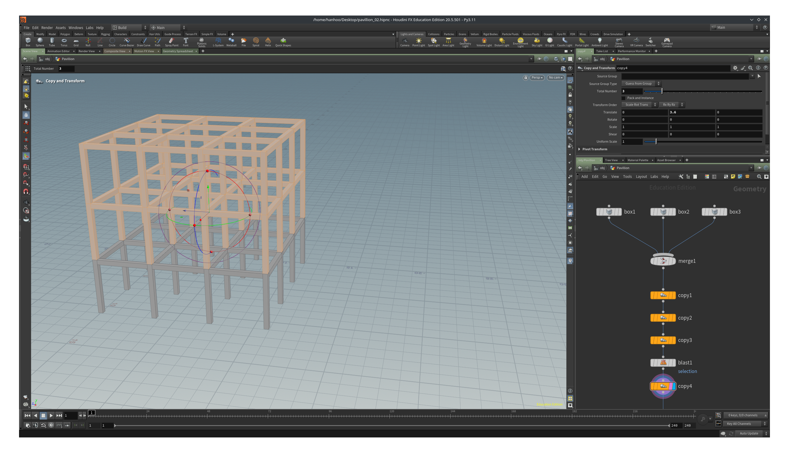
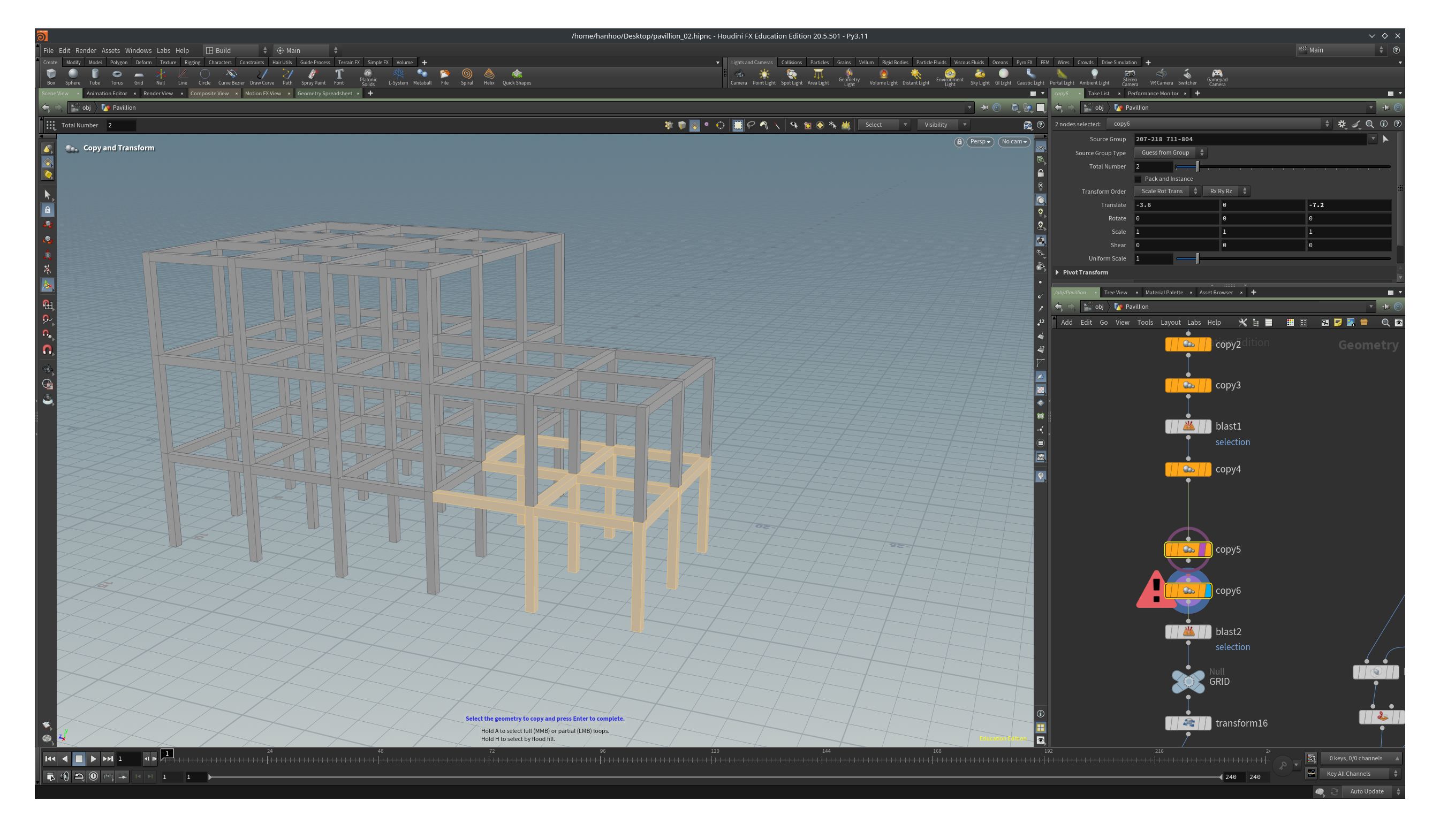
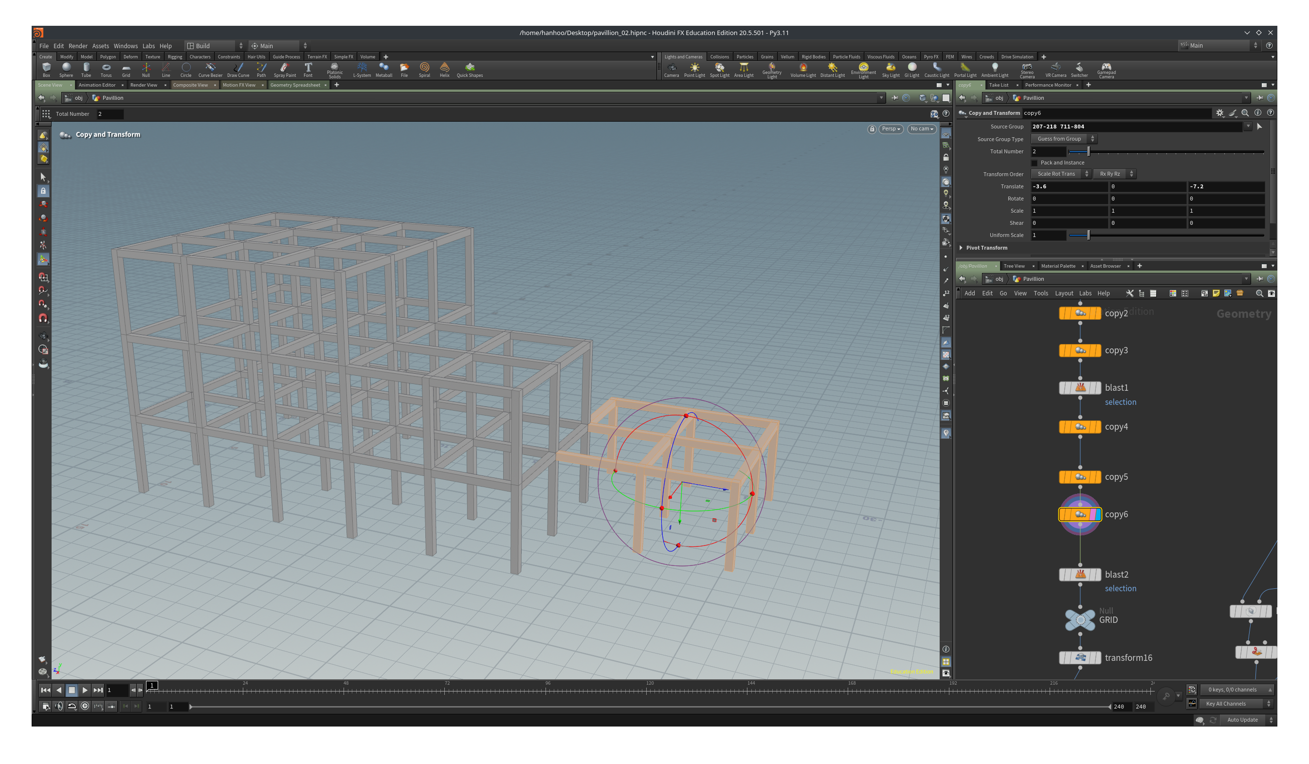
Almost there. We have two more cubes to make. We can use the geometry we created so far as a basis. From this geometry, select the columns and beams as on the pixture below, then duplicate it by -7.2 in the z-direction. Total Number stays at the default value of 2.
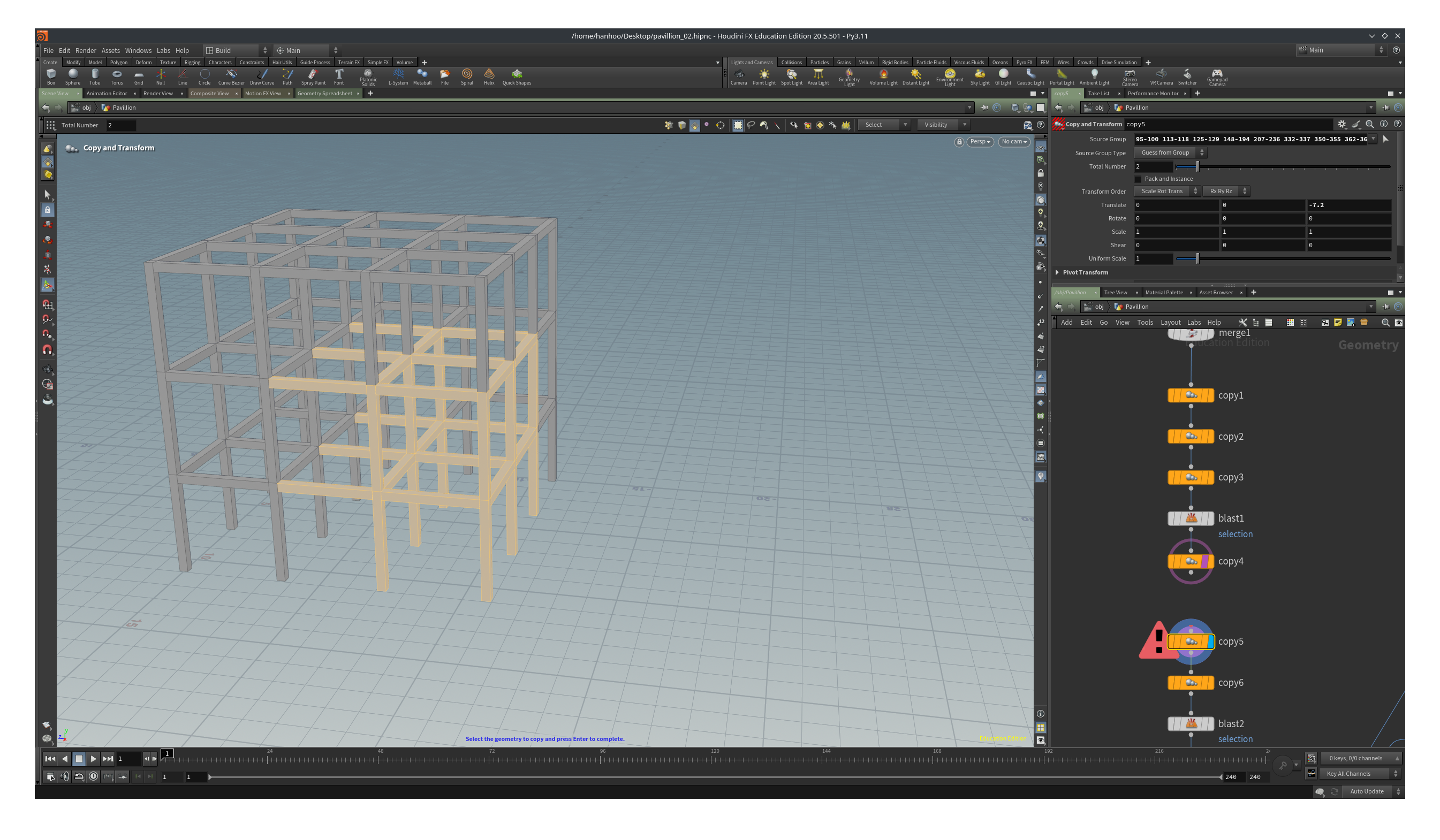
Now we create the last part of the structure, select the folowing beams and columns and duplicate it -3.6 in the x-direction and -7.2 in the z-direction.
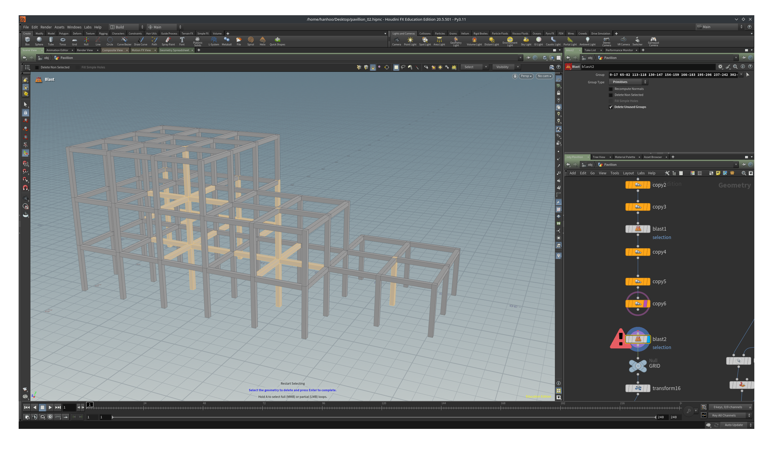
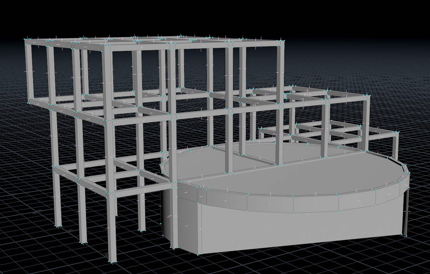
Our structure should now look something like the image below. Looking at the pictures of the pavillion we’ll see that there are some cuts in the structure so we need to delete some beams and columns.
Select the following beams and columns and delete them with a Blast node. Deleting the geometries will leave some gaps which we will fix in the next step.
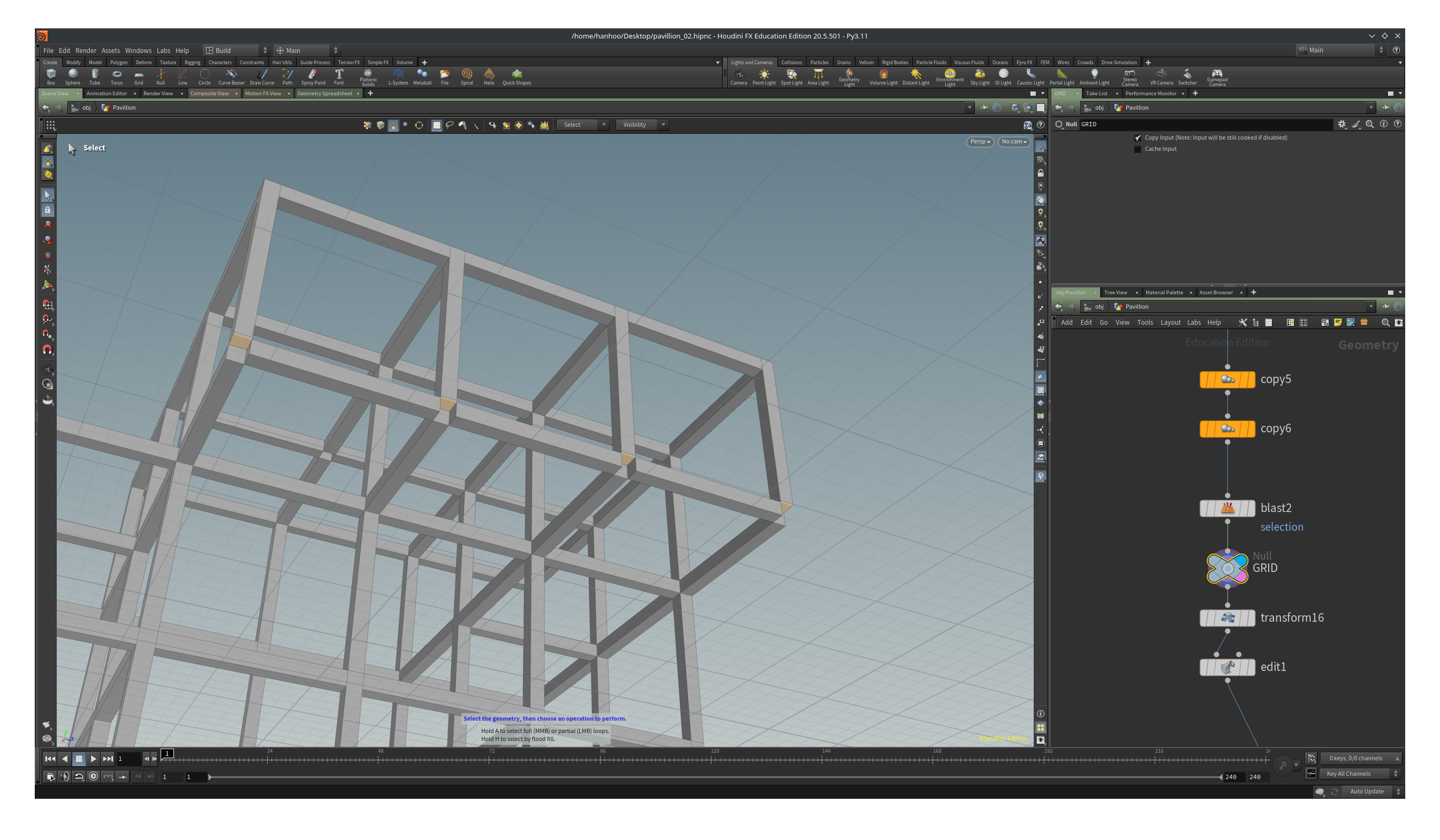
As you inspect your geometry by moving around in the scene you will see that there are some gaps between the connection of the beams and columns.
We can move around by pressing the spacebar and then use one of the mouse buttons to dolly (space + LMB), pan (space + pressed MMB) or zoom (space + scroll wheel / RMB).
For a refresher on navigating in Houdini see Viewing the scene
Select the bottom faces of the columns by going in the view pane, press s and then 4. Don’t double click but shift click on each of the four faces. With the face selected tab->transform. Move the faces down by -0.3, e.g. the Translate parameter should read 0, -0.3, 0.
For the holes in the beams on the top we are going to use another technique.
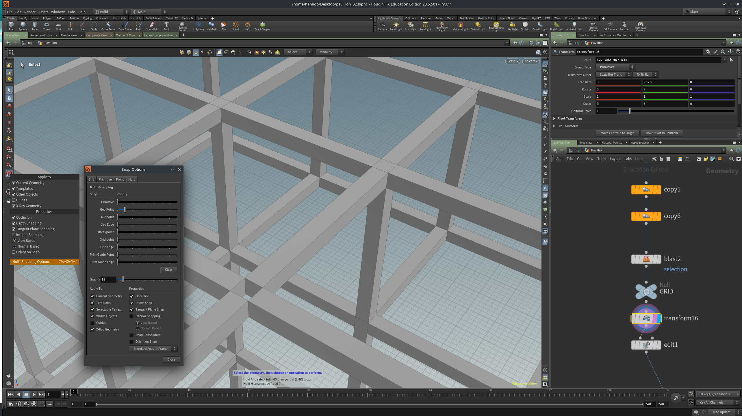
RMB on the magnet handle in the left tool bar and select Multi-Snapping options (all the way at the bottom, shortcut Ctrl+Shift+j). Drag the Midpoint slider to the right, this is the snapping importance weight. Then LMB on the magnet to make snapping active.
For more information on snapping see Snapping, construction plane, and alignment
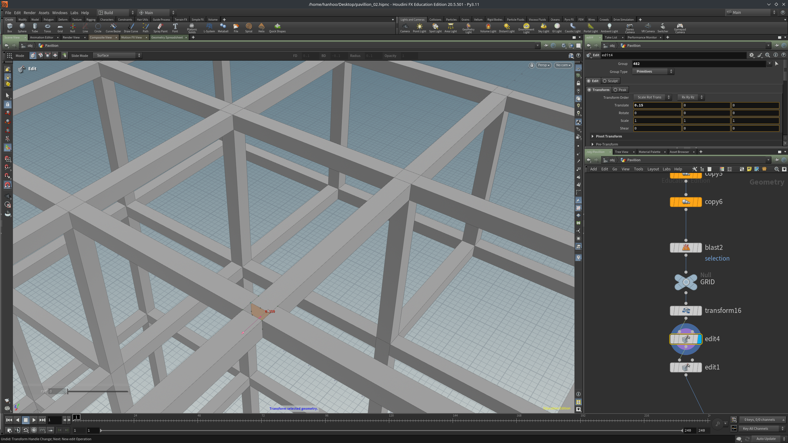
Select the end face of the beam and tab->edit. You will see a translate and rotate handle on the face. Drag the blue handle until you gently snap to the middle point of the one of the perpendicular beams. You will get some feedback that says you have moved the face by 0.15 units (Houdini uses S.I. units).
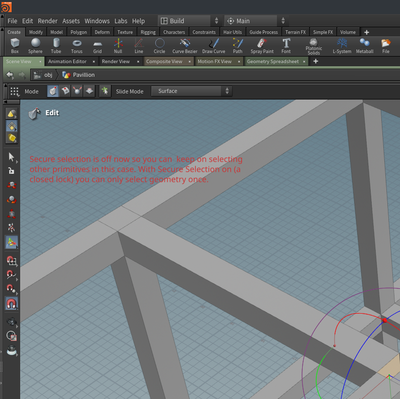
We can now select all the other faces and snap them to the midpoint of the perpendicular beams. If you are unable to select other faces while using the Edit node, turn off Secure Selection (see image below).
We have now are main structure and can move on to the next chapter; the round exposition room on ground floor.
Modeling an orthogonal pavillion in Houdini 3/6
The Exposition Roomlink copied
When we look at the pictures of the Expostion room on ground floor we see that it is basically a tube with a big cut for the entrance.
In the view pane press tab->tube, set the Radius to 7.2, 7.2 and the Height to 3.6. Use a transform node to move tube1 to right top most edge of the big cube structure. You can turn on point or geo-edge snapping to place it exactly. The transform is 10.95, 1.8, -10.95. You can switch to top view to make it even easier: press space+b in the view pane to switch to a 4 window view, then place your mouse in the top view and press space+b again to make it a single window view again.
We want to have proper walls so we are going to give the tube some thickness by extruding the faces. Select all the faces of the tube in the view pane and press tab->polyextrude. You can adjust the distance of the extrusion with the handle (the red line or with the slider dist in that appear in the view pane’s left top corner). Of course you can also place a polyextude node in the network pane, wire in the transform and change the parameter dist on the node to -0.3. We have to tick the Output Back option in the Polyextrude node because we are suddenly missing or outer wall!
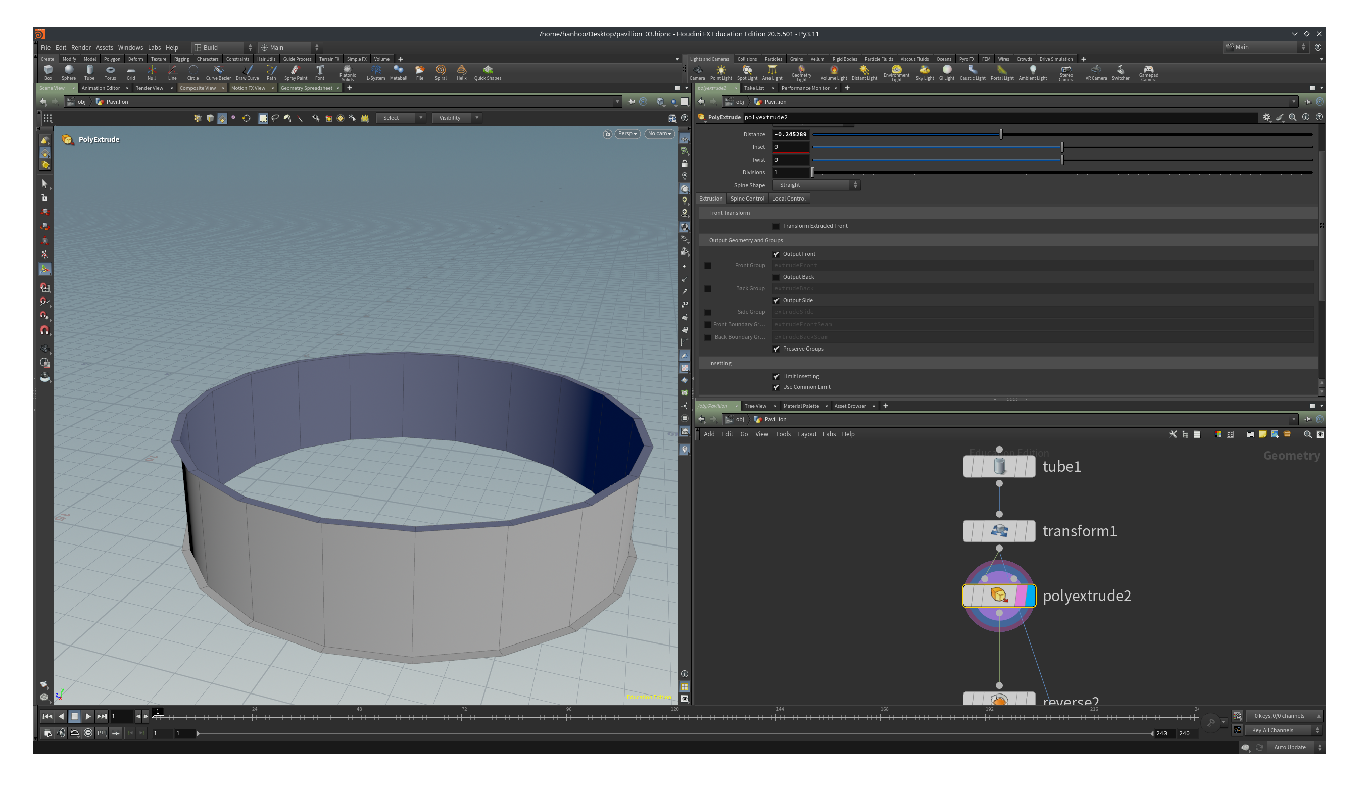
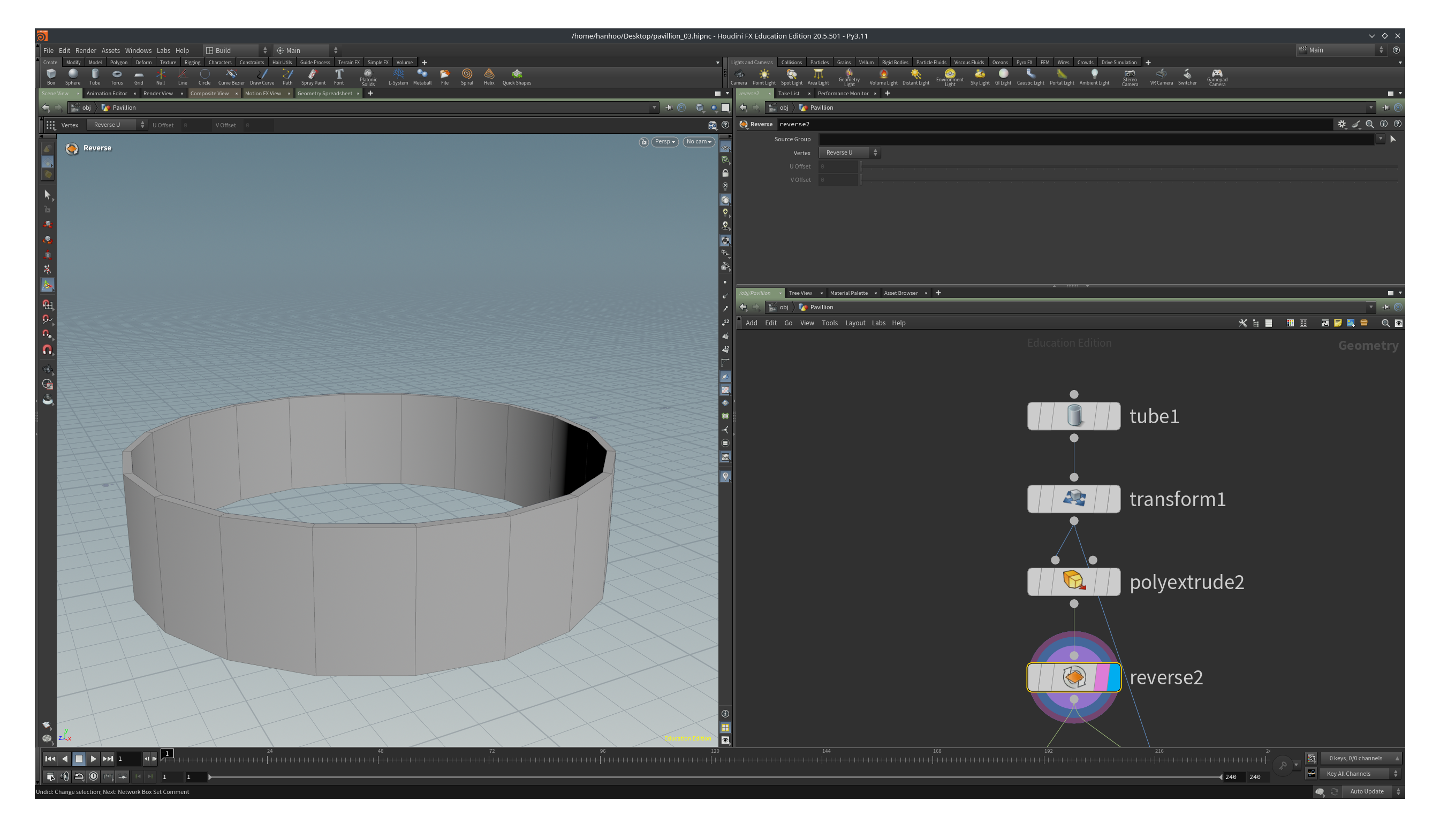
If we tick on the Output Back we have another problem. Although it looks like we have a solid tube now, the color has changed to a darkish grey. This means we are looking towards the back of our surfaces. We have to fix this because we will run into trouble later with rendering (either rendering in Houdini itself or in Unreal). We can reverse the normals with a Reverse node. Attach it to the polyextrude node and you will see that we have our boring greyish color back.
So far we mostly have viewed our scene in Smooth Wire Shaded mode but we can toggle to view our scene in Wireframe mode by pressing w in the view pane. There is an icon, a cube just left above the icon where we set the Create in Context, where we can select different view pane rendering styles. Viewing the scene in wireframe makes the part below a bit easier.
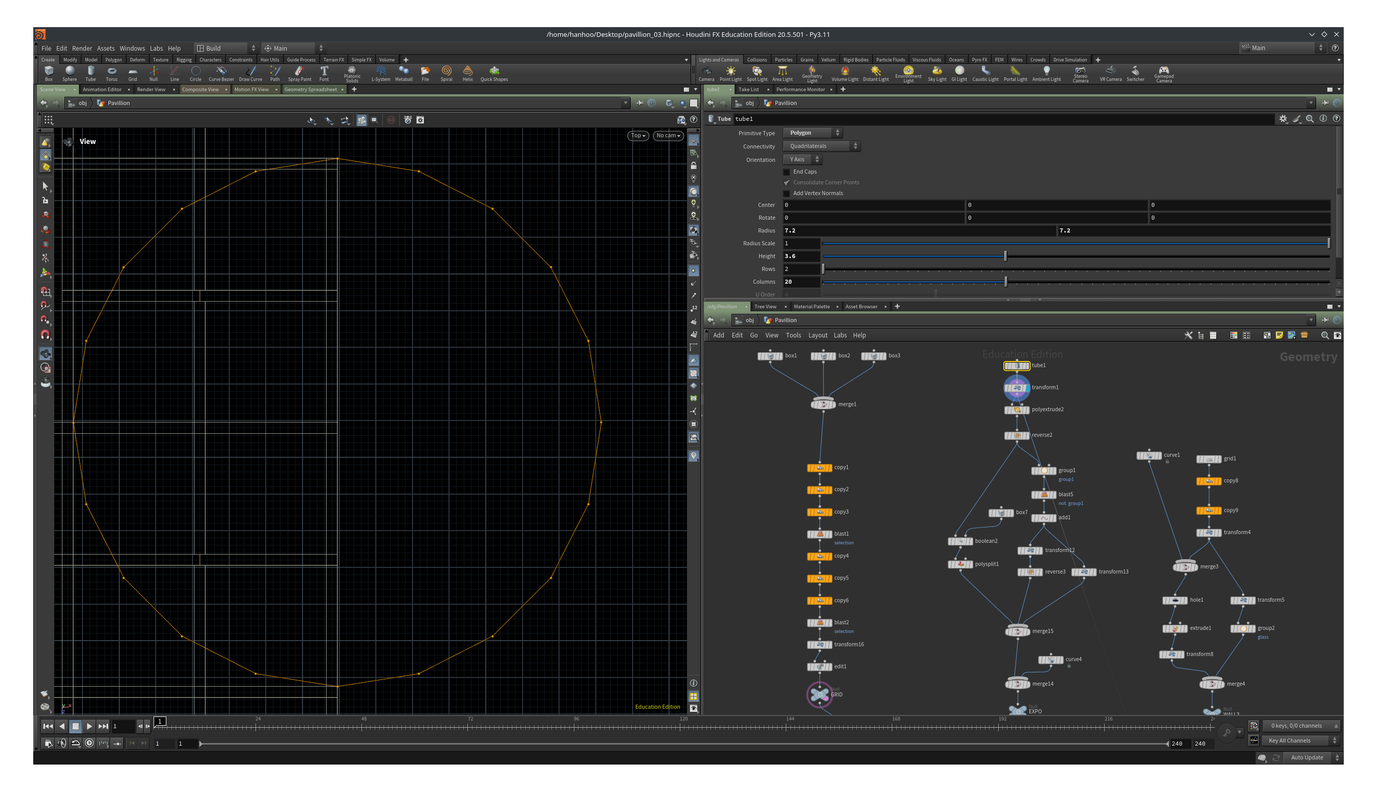
Set the view pane to top view and press the Escape key so that you are in View mode. Then:
- Make the grid structure visible as template by clicking on the template flag of the final node of that part of the network.
- Toggle the display on the transform1 node.
- Click on the tube1 node so that it is selected (it should have a yellow border).
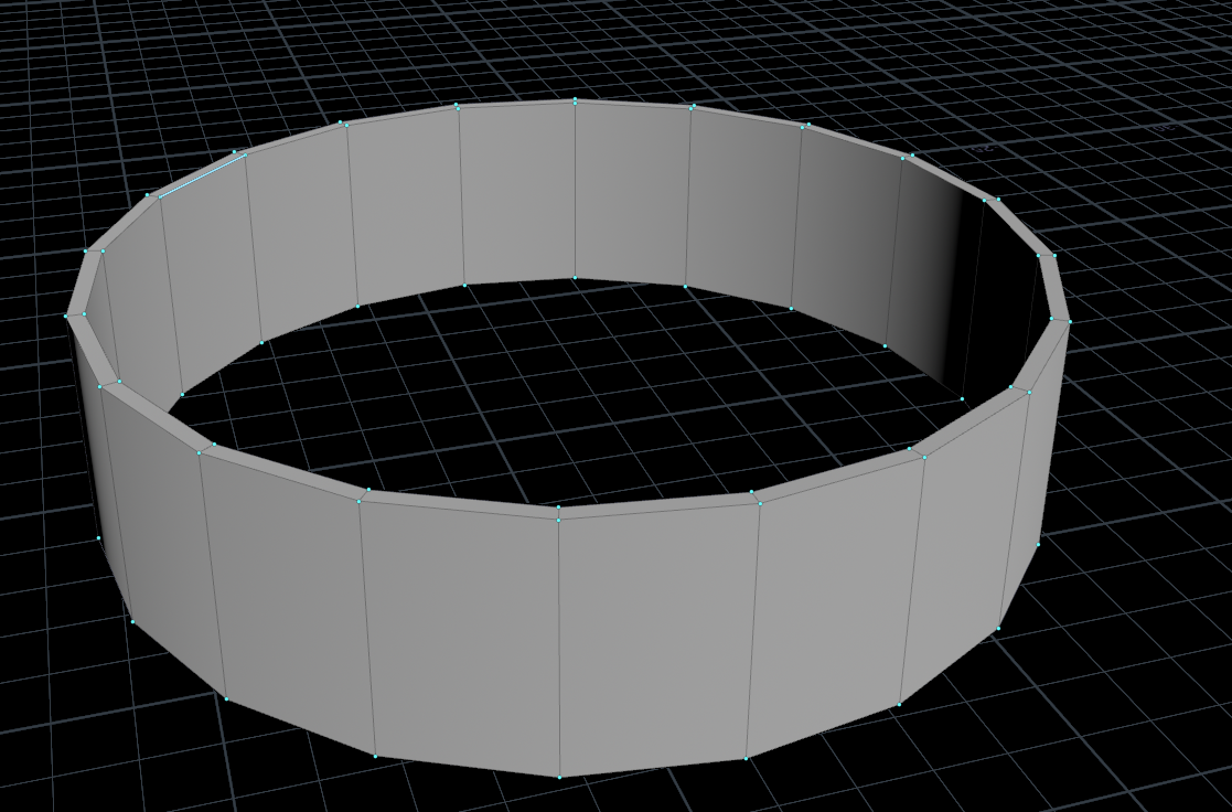
Adjust the Columns parameter on the tube1 to so that there are two points aligning with the corner points of the beams/columns. In the example it is 20 columns.
See this page for all the different node flags: Network types and node flags and page 8 of the Houdini Foundations pdf.
We are now going to make the roof and ceiling of the expostion space. We could create a circle and place that in the center of the tube but we can also use the geometry of the tube as a starting point.
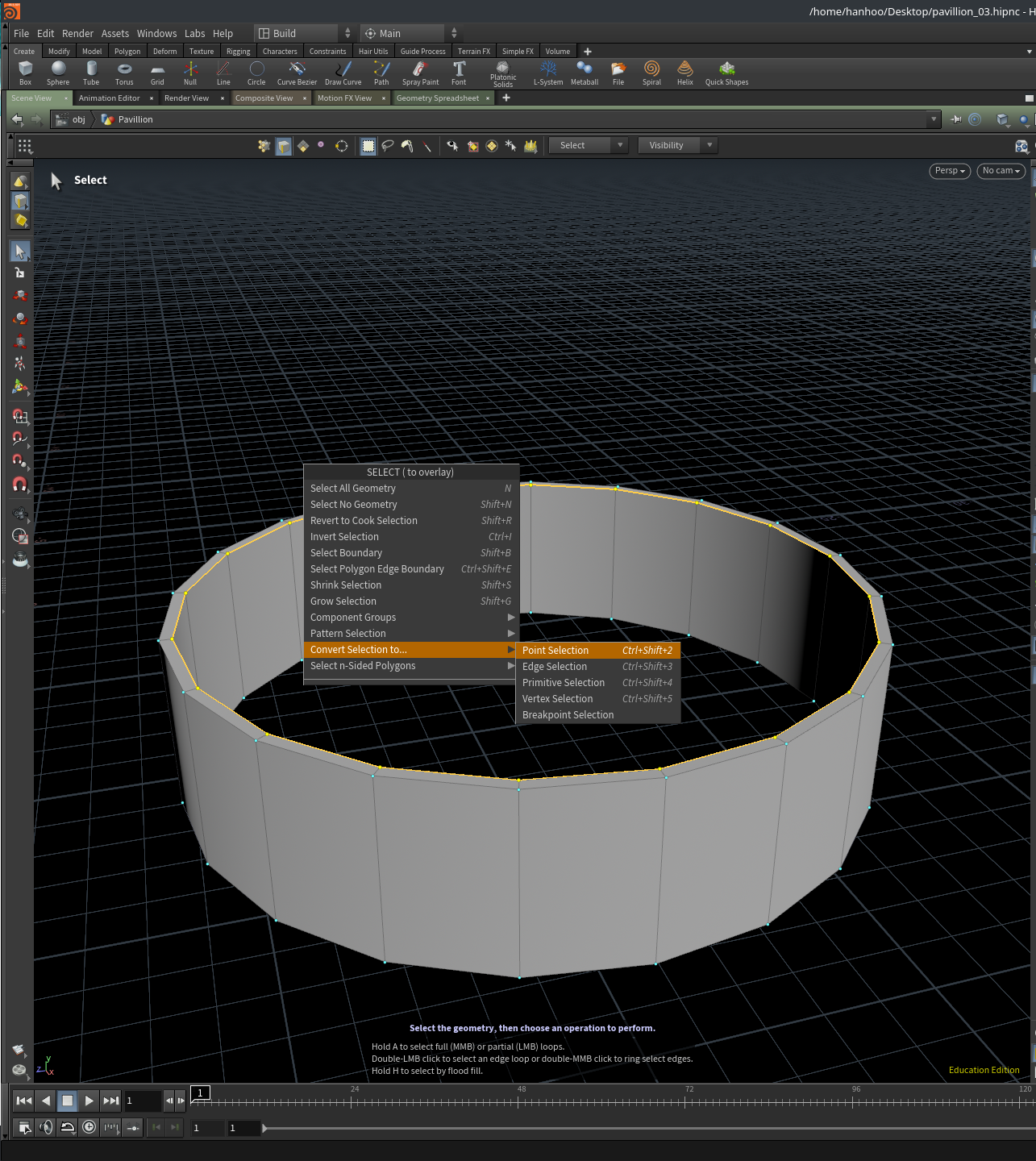
In perspective view and in the view pane, press s then 3 to start selecting edges. Select an edge on the inner top part of the cube and then double click. A whole edge loop has now been selected. With the edge selected, right click in the view pane and a menu will pop up. Click on Convert Seletion to… and then click on point selection.
We can create a group of these points by tab->group in the view pane. By default the group name will be the name of the group node, in this case group1.
We delete the points by connecting a Blast node to the group1 node. In the blast node we can type group1 in the Group parameter or use the drop down menu (arrow pointing down at the end of the input field).
So, we now have some kind of half like tube structure. How is this going to help us? The answer is not. The roof and ceiling should obviously be the size of the edge loop/points that we selected previously. So we want to keep the points and use them for some further operation. Luckily there is a Delete Non Selected toggle on the blast node. Ticking it will delete everything except the points.
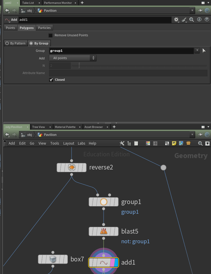
We can create a circle of these points by adding an Add node. Connect the Add node to the blast node and then click on the polygons tab and in the sub menu on the By Group and set Group to group1 and toggle on Closed.
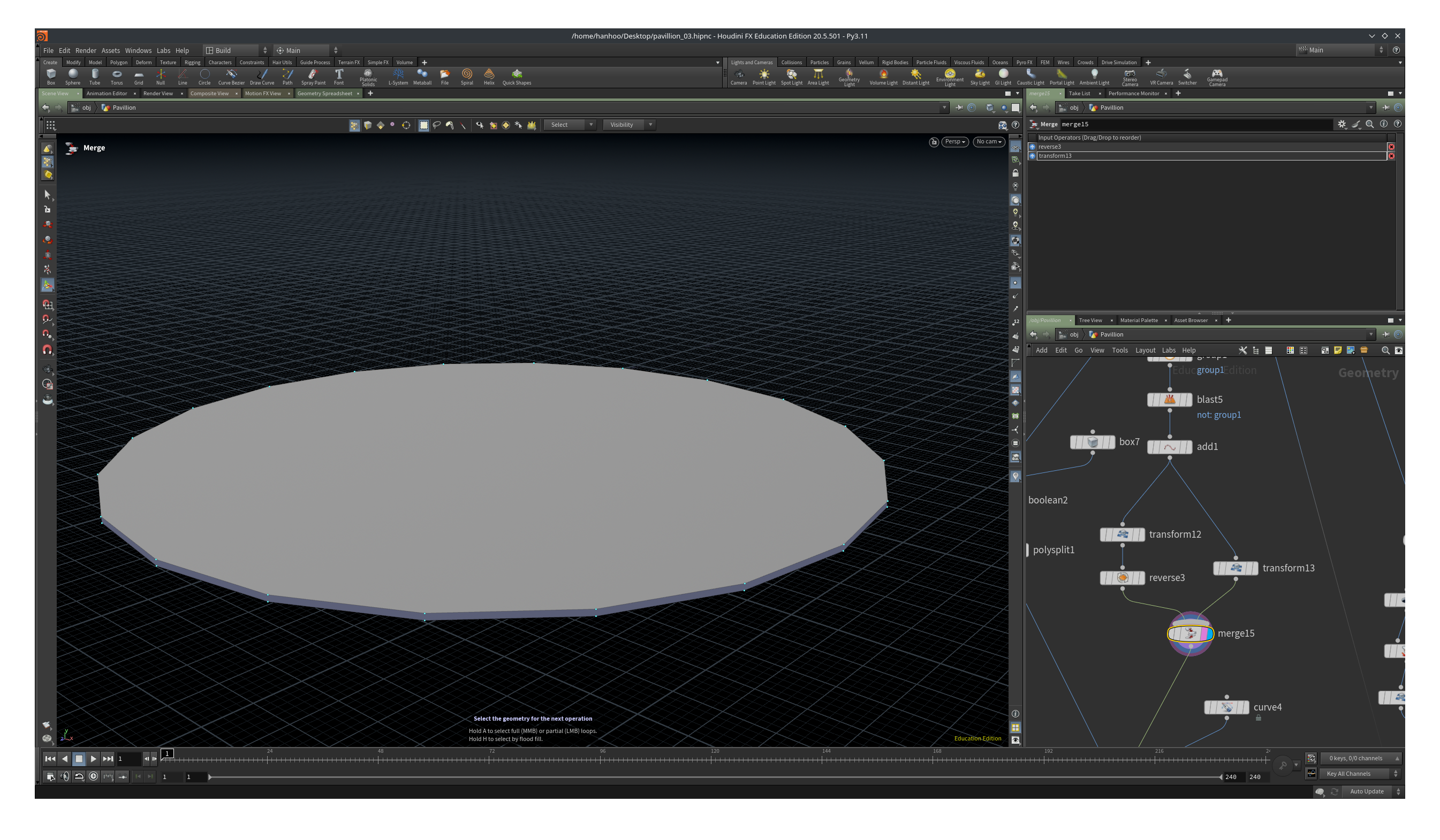
Move the roof down -0.1 with a Translate node and the ceiling with -0.2. These are two seperate transforms, each in their own “branch”. So each Transform node is directly wired into the Add node. Both circles have the same normal orientation, e.g. they both point down (or up). Add a Reverse node to one of the Transform nodes so that the roof’s orientation is pointing up and the ceiling’s down.
Merge the two branches with a Merge node.
We have now two more things to do, create the cut for the entrance and model the entrance itself (this is just going to be a single closed curve, nothing fancy).
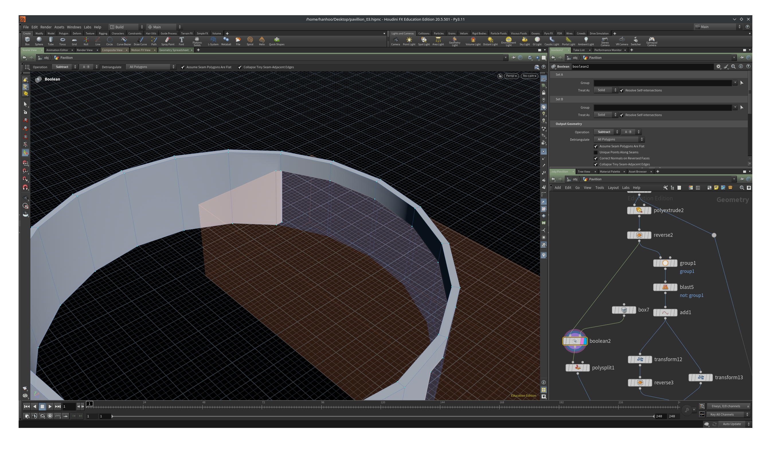
We start with the cut in the facade. Place a Boolean Subract node (tab->Boolean Subtract) and a Box node. Wire the reverse node of the solid cylinder into the left input of the Boolean node and the Box in the right input.
Adjust the Size and Center parameter of the box node to place the cut in the right position. In the example it is 6, 3.6 and 12.7 for Size and 15.5, 1 and -8.8 for Center.
That looks like a nice clean cut doesn’t it? Well, no. let’s inspect the geometry a little bit closer.
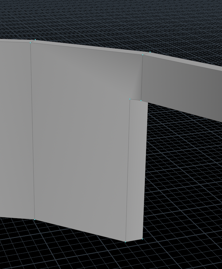
You see that there are some shadow artefacts on the geometry which could be an issue with rendering. Even worse, if we want to export this geometry to Unreal, Unreal will start to complain! Unreal is really picky when it comes to geometry, it accepts faces made up of three points (triangles or tris for short) or of four points (quadileteral or quads for short). We can fix this by splitting the faces using the Knife node and the Polysplit node. A demonstration is given in the video below.
With the Knife node we create a horizontal edge loop the same height as the opening. By turning on point snapping we can place the handle of the Knife tool accurately.
We then still have some faces that consits of more than four points. We fix this with the Polysplit node. The node was already used once in the demonstration so you can pick it from the bottom of the tab menu. Houdini remembers the last 5 commands you used.
By turning on Snap to perpendicular (RMB when the Split node is active and the menu appears), we create nice rectangular faces. The last point is not strcitly perpendicular but close enough. If it looks good, it is good!
With the second Polysplit we split all the way through till we finish on one of the points of the opening. If we didn’t split the bottom face, we would have a point on the edge, creating a five sided face again!
Now all that is left if the facade. Lay down a Merge node and wire in the roof, ceiling and the walls. Make sure point snapping is turned on.
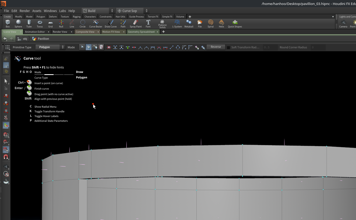
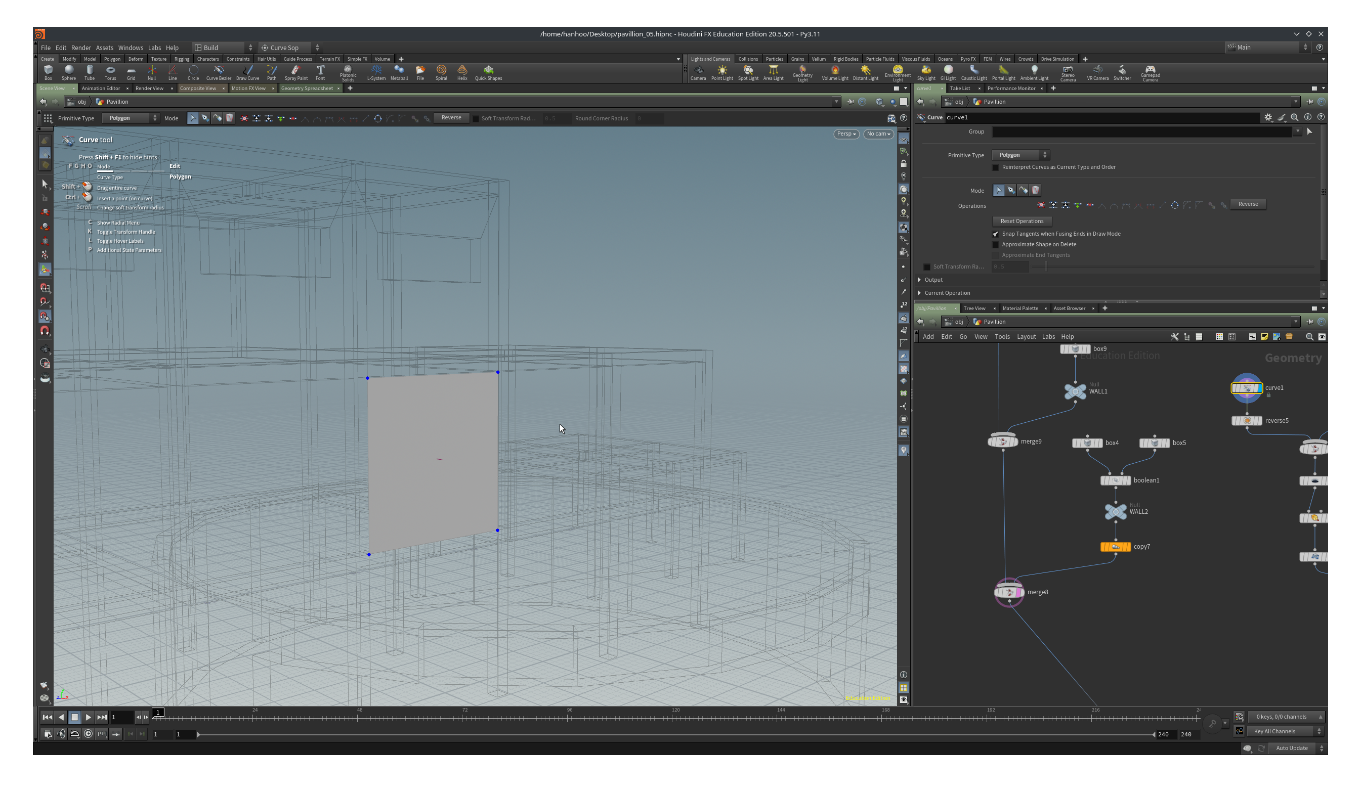
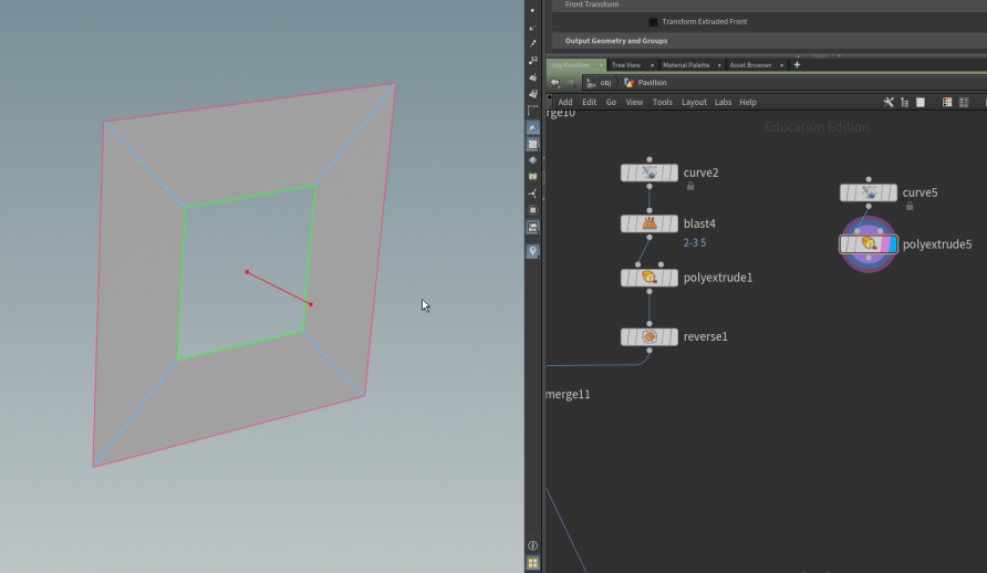
In the view pane type tab->curve. Now the curve tool comes with a whole set of options, sub menu’s and toolbar buttons. You can find additional information on the Curve documentation page. By default you are in draw mode and you can switch modes by pressing, F for edit mode, G for draw mode (and there is H and O as well but we ignore this for now). You see a red dot under you mouse, that is the point you are going to place.
Try to place it close to the points of the opening and then draw a curve from left bottom, left top, right top, right bottom, and to close the curve we click on our first point. It probably will take some practice. If the curve is closed it will turn into a boring grey surface.
We are almost done. There is a gap between the ceiling and the facade so we have to fix that.We are going to drag the points up to the ceiling. Make sure point snap is on. Press F to go into Edit mode. Select the two top points of the curve. If you see a handle in the middle of the top edge of the curve you are fine, else press K. Drag the green handle up and while dragging hover the mouse over one of the points of the ceiling. You hopefully see that the edge snaps to the right height.
Connect the curve into the merge node of the walls, roof and ceiling and we are done.
Now we only have to create the walls and stairs, and our pavillion will be finished.
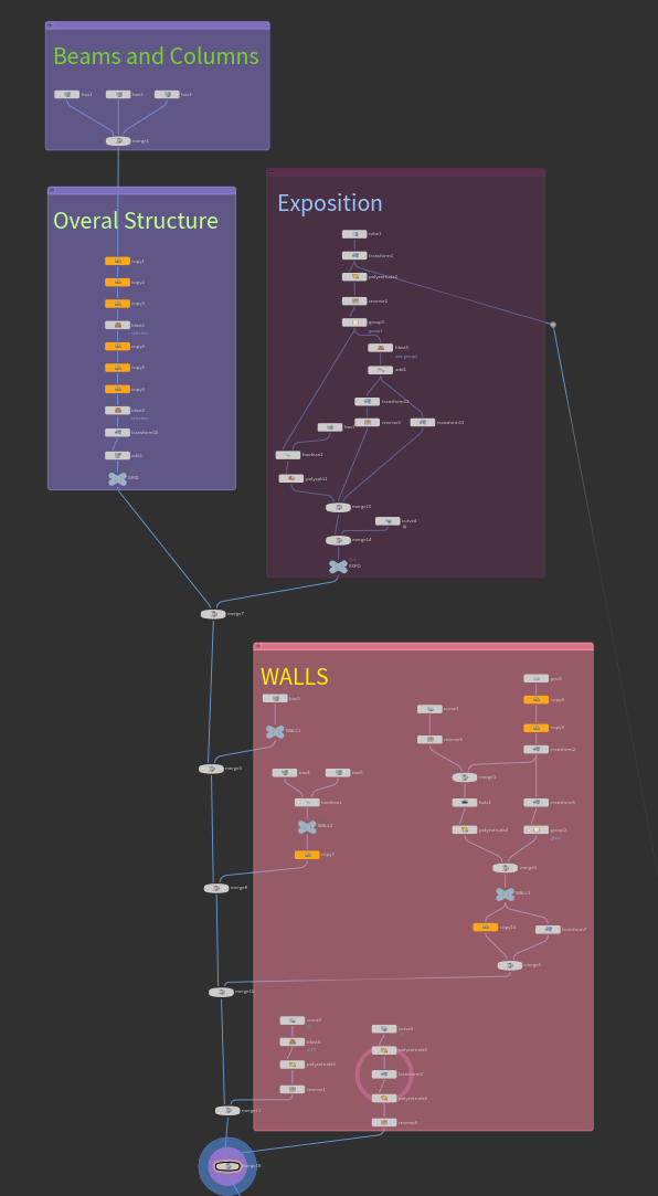
The network now looks something like the image below. The text and colored boxes are used to show the different chapters so far.
Modeling an orthogonal pavillion in Houdini 4/6
Adding Wallslink copied
In this chapter we will be filling in the walls of the pavillion. We will use several different approaches to create the walls. We start with a very simple solid wall.
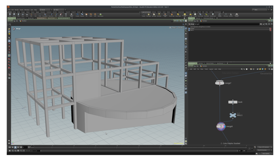
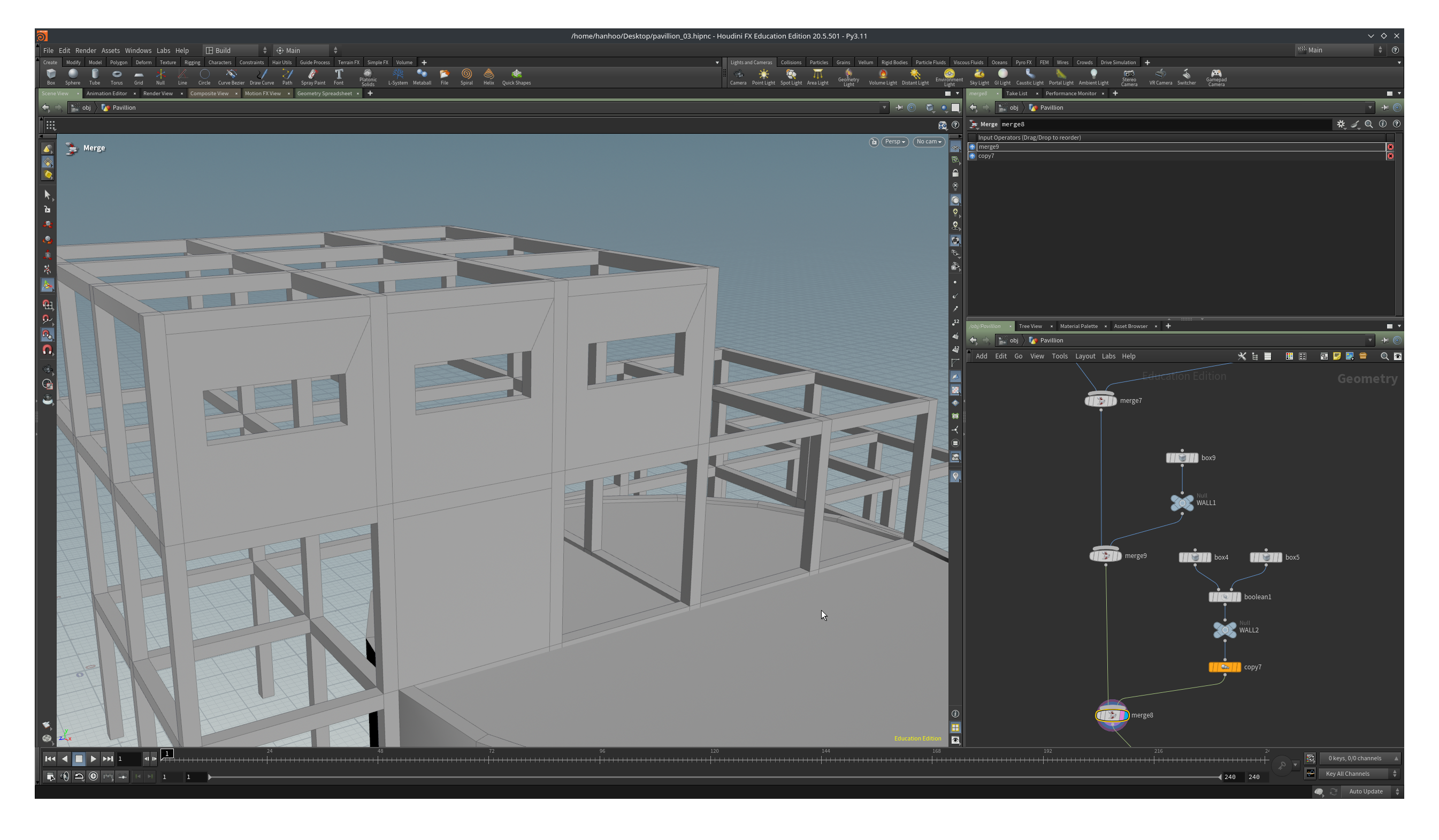
Add a new Merge node after the last node of the previous chapter (the merge node you see at the top in the network pane in the image).
In the view pane add a box (tab->box). Make sure Create in Context is turned on (see first chapter). Turn on point snap. Drag the handle at the centroid of the box to a point of the beams or columns in the grid where we want to place the wall. Switching to wireframe mode makes this process a bit easier (press the w key in the view pane). If somehow you lose the handle of the box press enter in the view pane with the Box node selected in the network pane.
Drag the handles on the faces of the cube towards the side of the beams and columns. When you hover with your mouse over one of the points on the geometry of the beams/columns, you will see that the handle snaps to that position.
Create another wall in the grid, one up and to the left of the wall we just created.
You can always check the parameters of the boxes if they show the correct values. A wall should be 0.3 thick, and have a width and height of 3.3. Also the center of the box should be multiples of 0.15. If the values are slightly off, you can type in the correct ones.
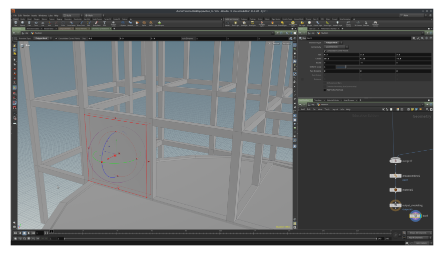
We are going to make a window in this wall using a Boolean Subtract. Lay down the Boolean Subtract node and wire in the box that is the wall in the left input. Add another Box, wire this one in the right input. Play with the position of the box to create an opening in the wall.
On the reference picture you see that we have three walls with windows on the top part so we add a Duplicate node, set Total Number to 3 and Translate to 0, 0, -3.6.
Add another Merge node and wire in the existing geometry and the newly created walls.
We are now going to make the walls with multiple small windows, like the ones you see in the pictures on the ground floor on the right of the pavillion.
We could use the boolean technique like above but there are always different ways to achieve a result. We are fist going to create a 2D layout of the facade element and then extrude it.
The facade elements are 3.3 by 3.3. We want to have 3 window elements in x and 5 in the y-direction. We want the windows evenly spaced. So we have some sort of formula, 4 spaces + 3 windows = 3.3 and 6 spaces and 5 windows = 3.3. If we choose 0.1 for the spacing it leaves us with (3.3 – 4 * 0.1) / 3 width for the windows and (3.3 – 6 * 0.1) / 5 for the height of the windows.
Add a Grid node and copy paste the formulas above in the Size parameter. You will see that the input fields, they are officially called channels so we will use that name from now on, have turned green. This tells us we have some expression in the channel. Click on the Size label to toggle between the value and the formula.
Set Rows and Columns to 2.
We now need to duplicate the single window in x and the y-direction. Lay down two Duplicate nodes in sequence. We are going to use the formula’s again to set the translation. We need to translate by the width or height of the window and add 0.1 for the spacing so the formula’s become (3.3 – 4 * 0.1) / 3 + 0.1 and (3.3 – 6 * 0.1) / 5 + 0.1.
| Duplicate horizontal | Duplicate up | |
| Total Number | 3 | 5 |
| Translate x | 0 | 0 |
| Translate y | 0 | (3.3 – 6 * 0.1) / 5 + 0.1 |
| Translate z | (3.3 – 4 * 0.1) / 3 + 0.1 | 0 |

Draw a curve that snaps to the pavillion grid.
We need to postion ouor small windows in the center of the curve we have just drawn. We will do this with a transform and with the help of the snapping tools.
Turn on multi-snap and set the “weight” for Midpoint higher than Geo Point (ctrl+shift+J opens the Snap Options window).
Make the curve visible as template
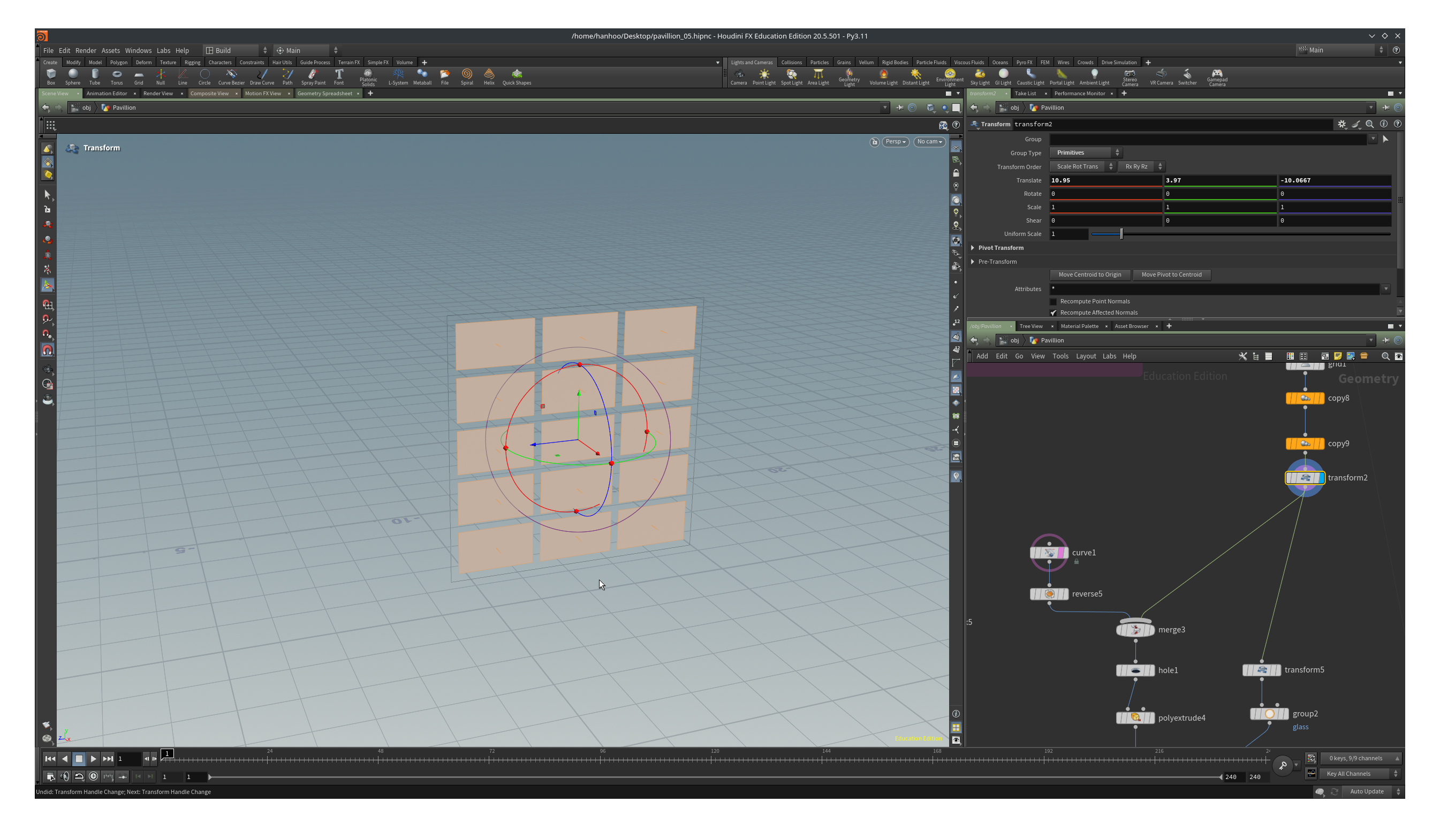
Select the 15 small rectangles in the view pane and tab->transform. The transform handle is located at the center of all the geometry.
Orient the view pane in such a way, with zooming out. tumbling, that you can see both the templated curve and the 15 rectangles.
Now drag one of the axis of the handle (the green, blue or red arrow) in the direction of the curve. While dragging move the mouse over or close to a mid point of the tamplate curve. Do the same maneuvre for the other two axis.
The 15 rectangle should now be inside the are of the curve.
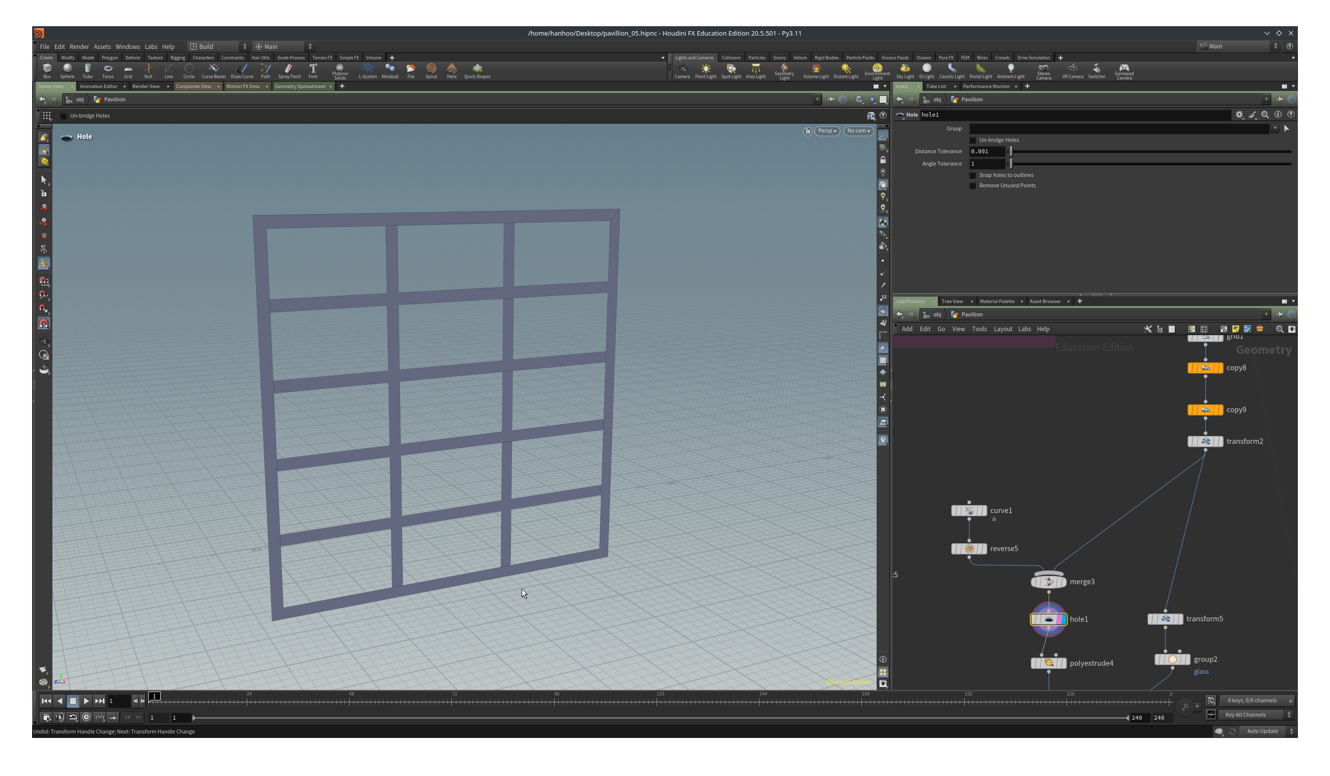
Merge all the rectangles and the curves and attach a Hole node to the merge. With the Hole node we subtract the rectangles from the curve and get something like the image below.
Connect the Hole node to a Polyextrude and set the extrude distance to 0.3. Turn on Output Back.
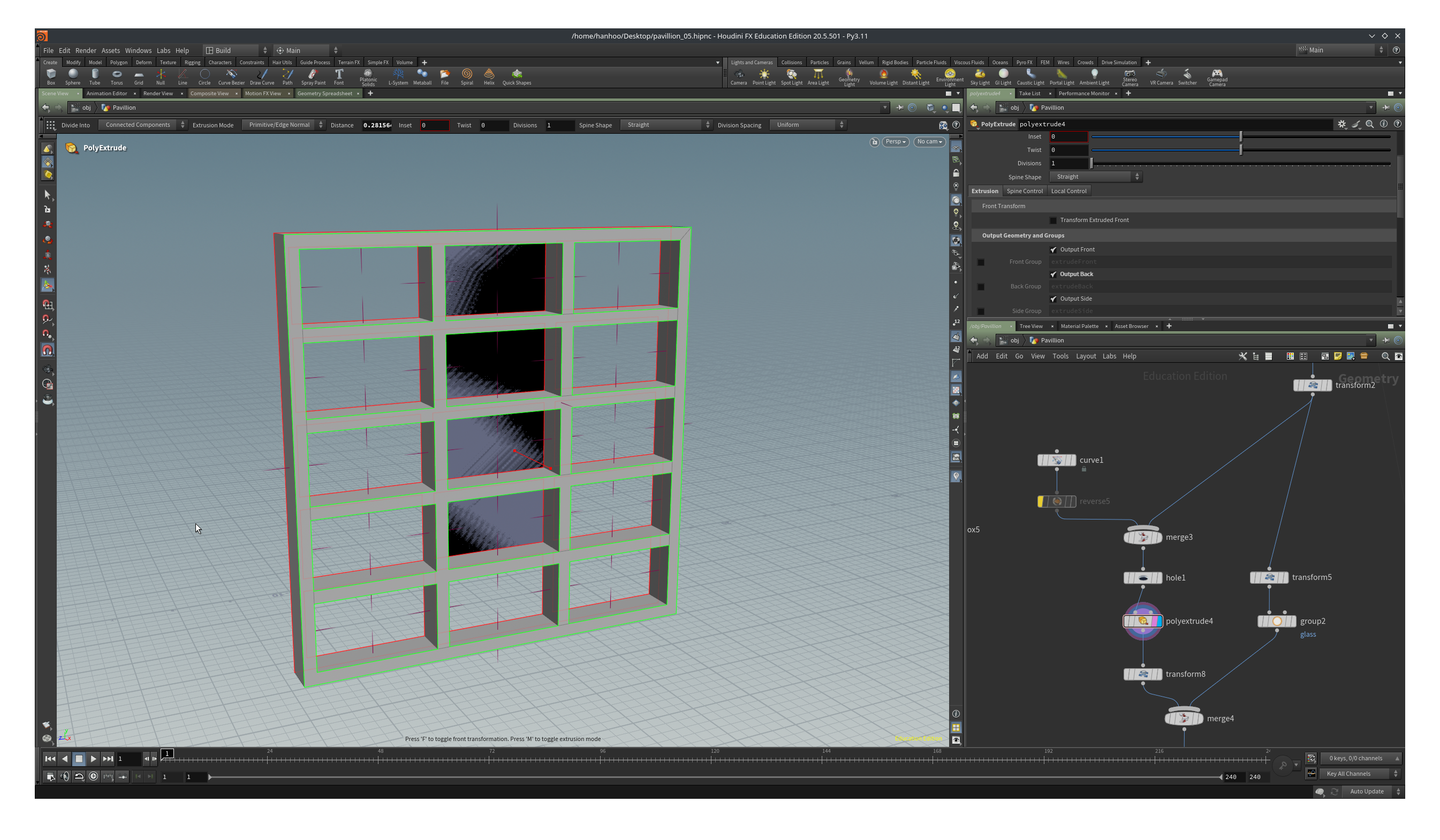
If you get some weird looking geometry as above you’ll have a problem. You can solve this by adding a Reverse node after the curve.
We reuse the rectangles for the glass in the facade but we don’t want it to lay flush with it so we transform it -0.1 in the X direction with a Transform node. We add a Group node after the transform and in the Group Name channel we type glass.
We merge the window frame and the glass with a Merge node.
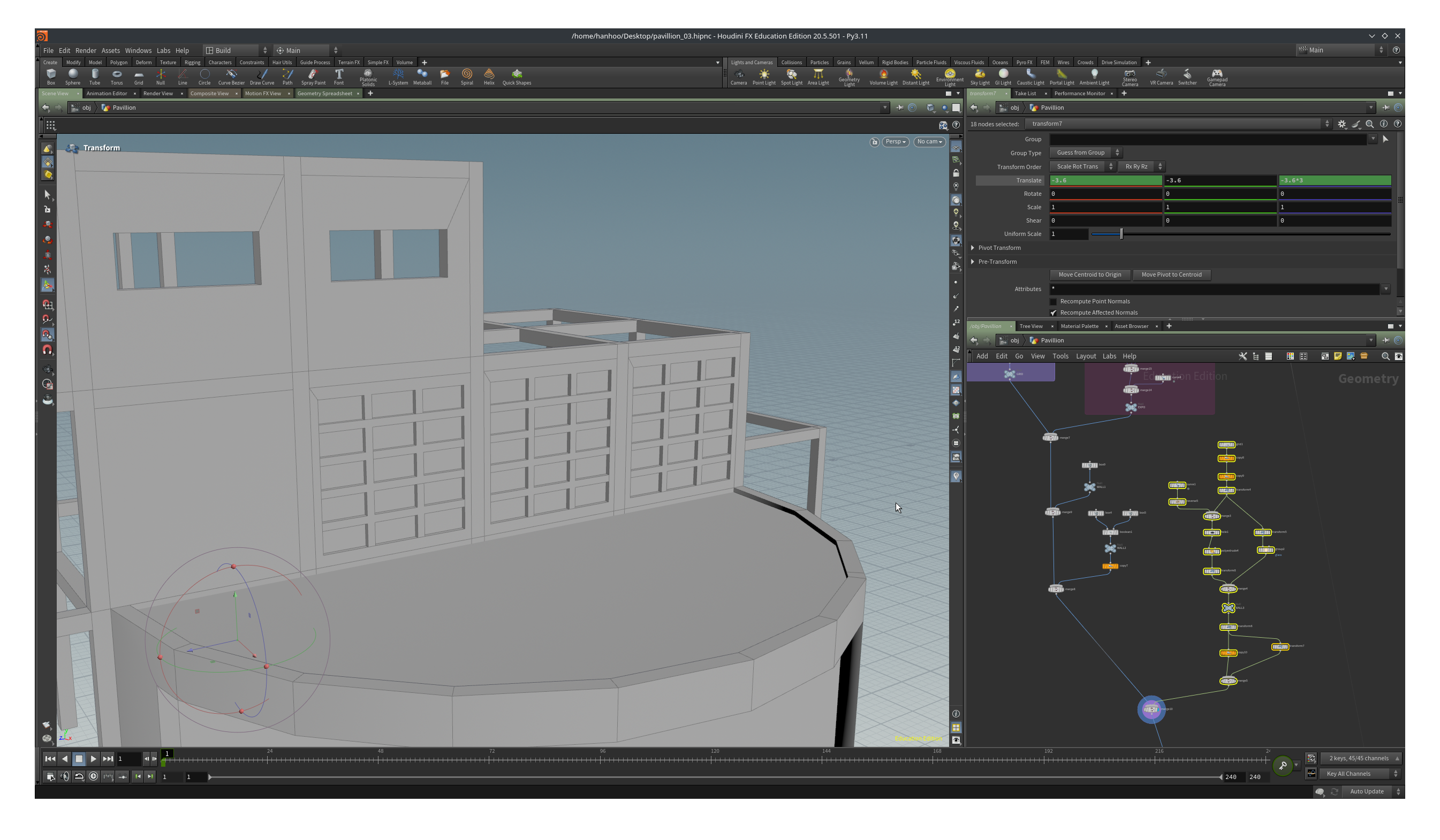
We Duplicate the wall element 3 times with a distance of -3.6 (Total Number is 3, Translate is 0, 0, -3.6)
We have one wall element on the ground floor so we transform our first element by -3.6 in X, -3.6 in Y and -10.8 in Z.
We merge the duplicate and the transform and we have now all our facades.
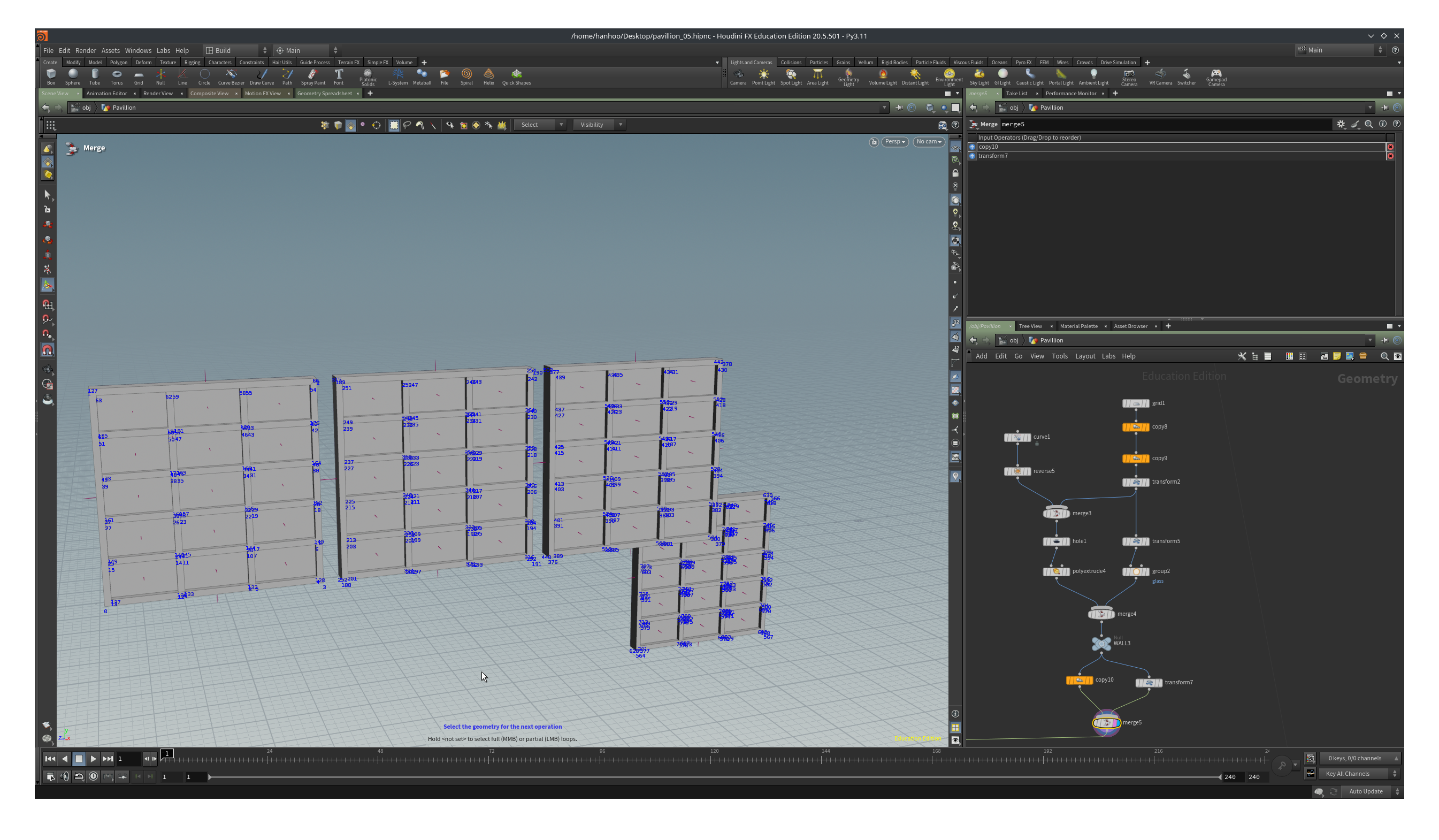
And then, as usual, we merge these facades with the rest of the pavilion.
We are going to close the top floor of the pavillion with some more walls.
With the curve tool we can draw more than one curve at once. Template the above geometry and start drawing curves on the sides but leave the first grid on the left and right empty. You should place some elements with the big windows there.
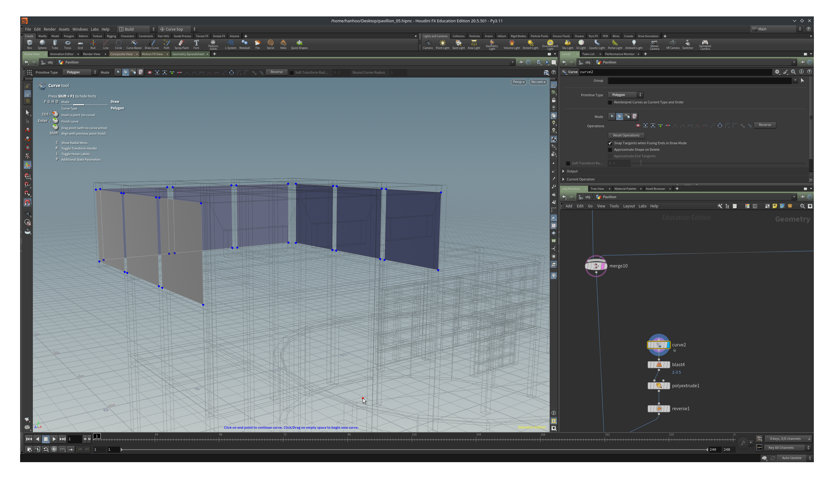
We have drawn too many walls so after the curve we can add a blast to delete the primitives.
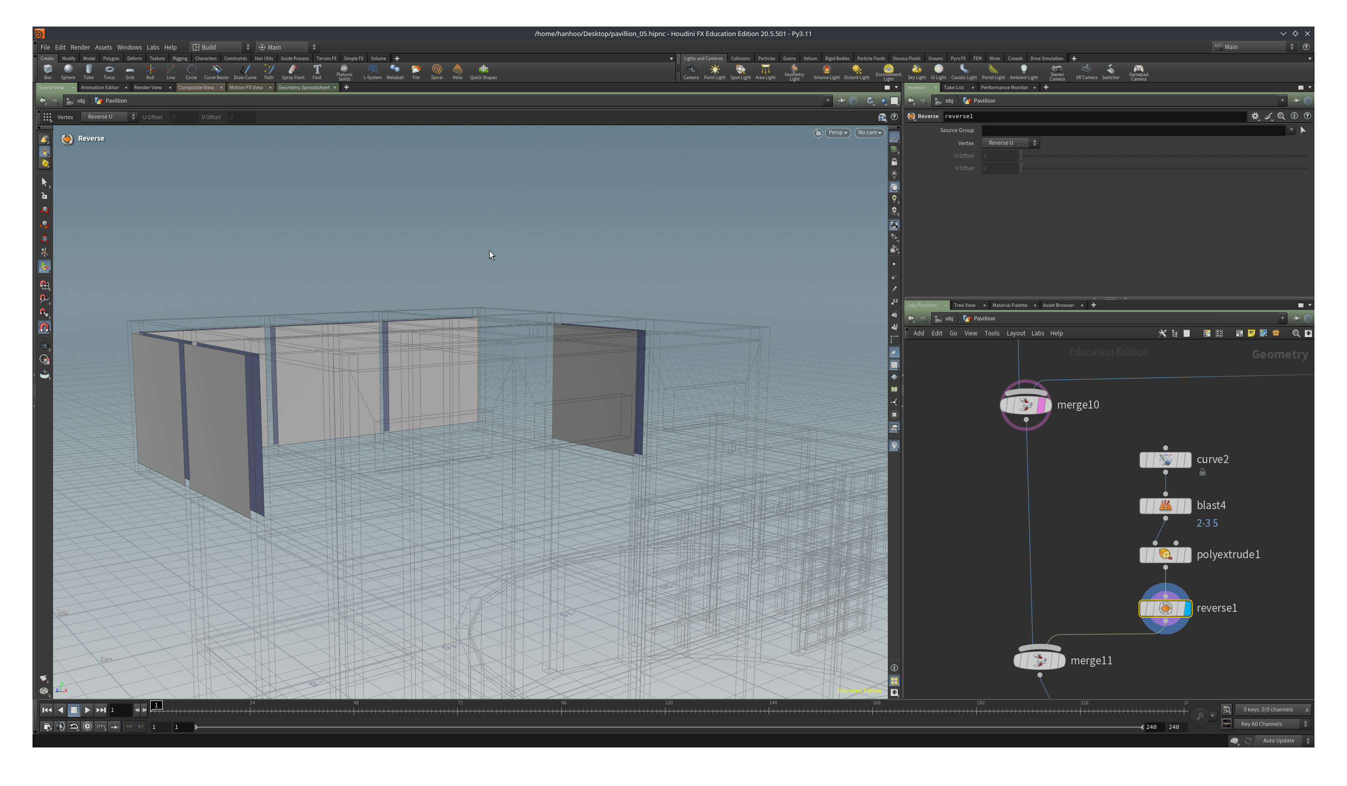
We can now extrude all the curves at once with a distance of –0.3. Turn on Output Back and turn off Output Side. We now only have surfaces for walls which is perfectly fine. Because the walls are flush with the columns we can’t see inside. Don’t model what you can’t see! (which means that there is a lot of extra geometry in this model that we don’t actually need).
We probably need to add a Reverse node…those normals are annoying aren’t they?
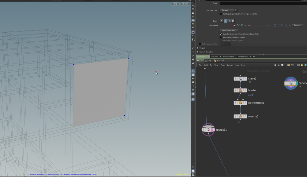
We are going to add one more wall and then it is up to you to add the missing parts in a way you see fit.
At the back of the top floor we are going to draw a curve again.
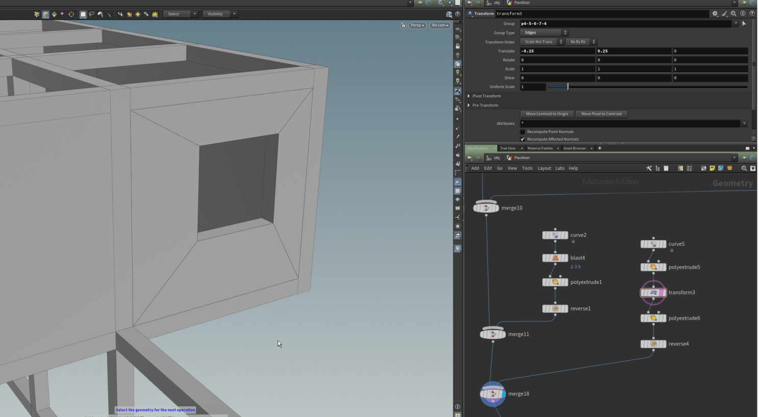
Select the wall in the view pane and tab->polyextrude. We are setting the Inset channel to 0.9 and turn off Output Front.
Add another polyextrude and extrude by -0.3. Turn on Output Back. Add a Reverse node and merge the wall element with the rest of the pavillion.
If we want to reposition the window, we can add a Transform node after the first polyextrude. In the Transform node, click on the white arrow at the left of the Group channel (top left in the parameter pane) and select the edges of the hole. Check that select by edges is turned on by pressing 3 in the view pane. Double click on an single edge to select the edge loop, and then press enter. A transform handle is visible, drag the axis handles to reposition the hole.
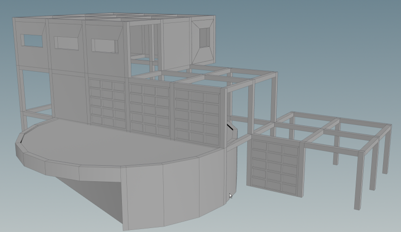
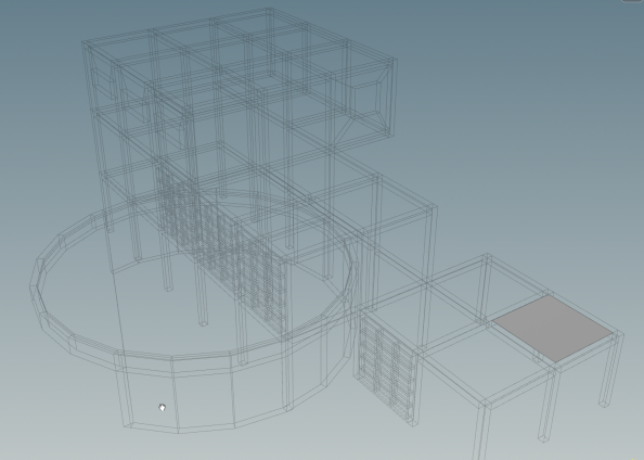
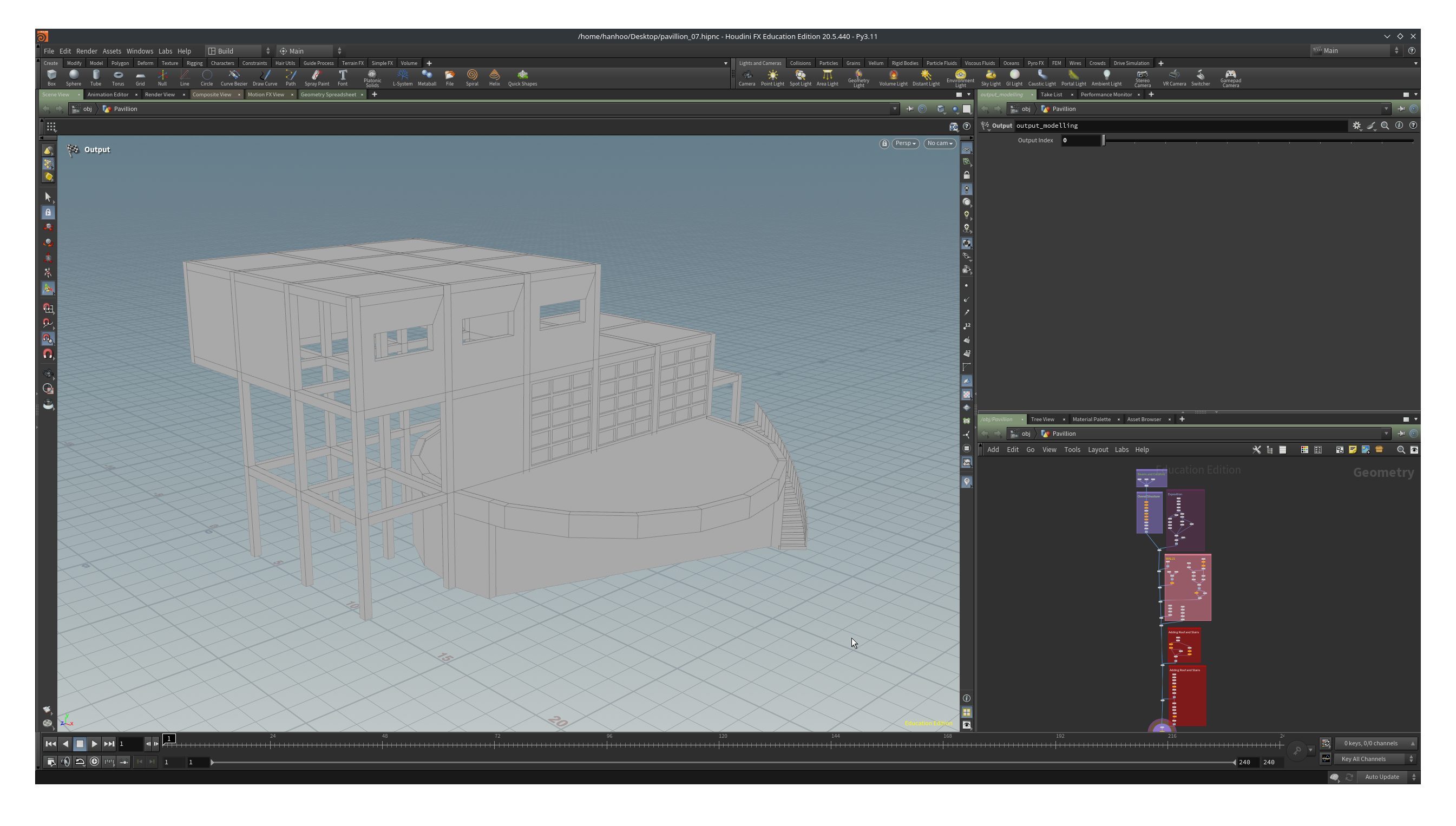
Our pavillion and network now look now something like the images below. In the next chapter we will add the stairs and the roof.
Modeling an orthogonal pavillion in Houdini 5/6
Adding Roof and Stairslink copied
In this chapter we will finalize the modelling part of the pavillion by adding a roof and the stairs on the side of the Expostion Room.
We will start with the roof, this is going to be super easy. The ingredients are one curve and one merge node and, three transforms and four duplicates.
Draw a curve in the top grid of the lowest “cube” part of the pavillion.
Attach a Transform node and move it down a little bit so we can see the beams stick out of the roof a little bit (for esthetical purposes). Attach a Duplicate and set the Translate to either 3.6 in X or Z-direction. Add another duplicate and set the Translate in the other direction, thus Z or X. We now have the roof of the small cube.
The two storey cube has the same roof layout as the small cubbe so we can just transform the lower roof to the right position. Add a Transform node after the last Duplicate and move the roof by 7,2, 3.6, 7.2.
For the roof of the three storey cube, we transform our starting curve to the right position, a translate in Z of 14.4 and 7.2 in Y, and then add two Duplicate nodes like on the lower roof, same settings except that Total Number is now 3.
We wire everything in a Merge node and we have our roof.
For the stairs we start with a Box. Set the Size parameter to 1.0, 0.15, 0.25. We are now going to place this box on the right side of the opening in the exposition room so add a Transform to the box and snap it to the point on the right side of the opening, outerwall.
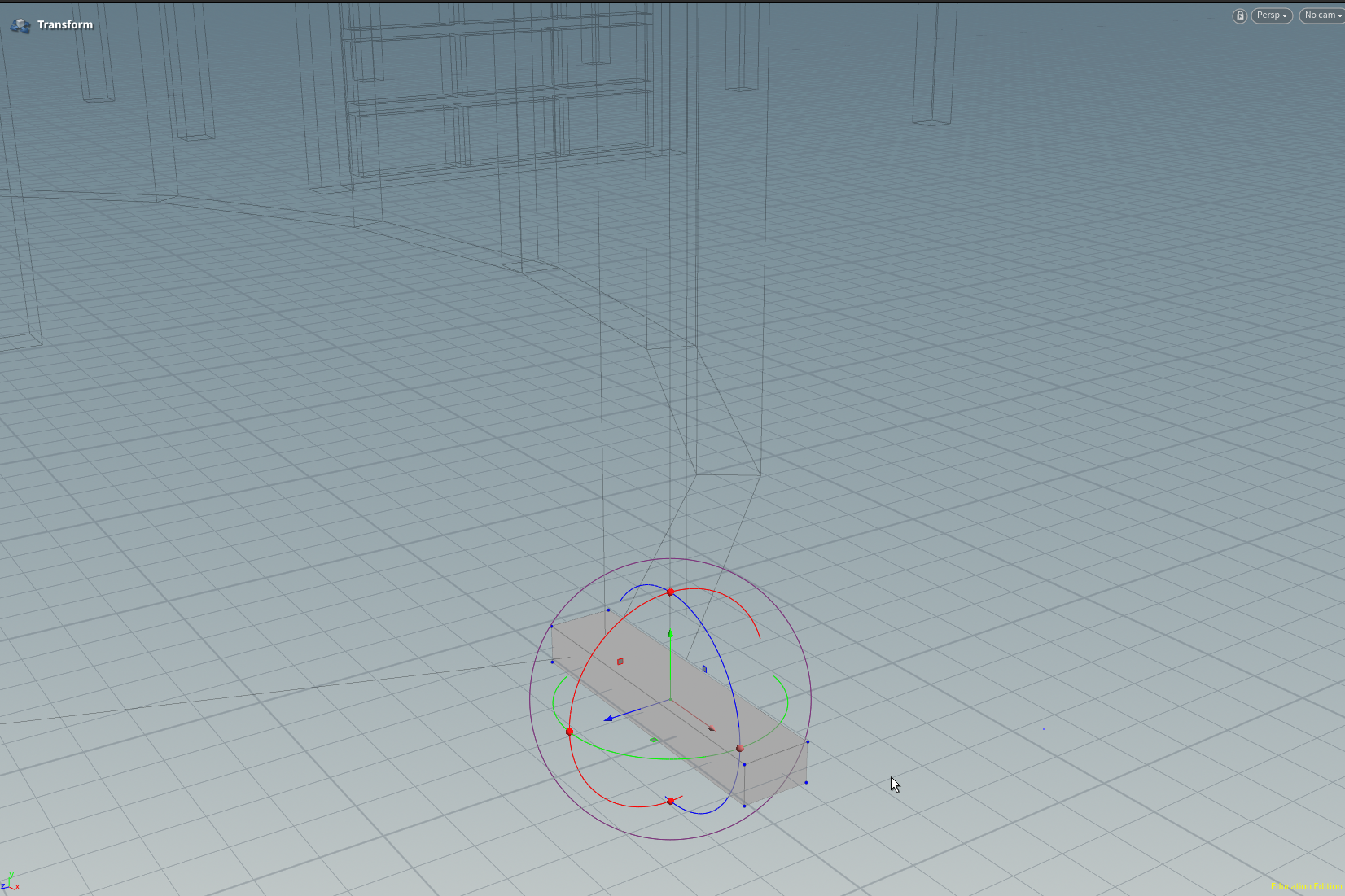
Select the geometry of the box in the viewport and tab->transform. A new handle appears at the centroid of our selected geometry. If we would have attached a Transform node in the network pane, the handle would have been located at the origin, which is inconvenient.
We can orientate the first step to the wall by aligning the handle with the primitive.
You can reposition and reoirent most of the handles, the exception being handles on geometry nodes like Box, Tube and Circle etc. To do that you:
- To place the handle in another position you can detach the handle by pressing the ‘ key (key next to the enter key). You can now drag the handle to a new position and then reattach the handle to the geometry by pressing the ‘ key once more.
- To reorient the handle you can press the ; key (key next to the ‘ key). With reorienting the handle, you rotate and possibly translate the handle.
We are first going to orientate the box in the right direction. Press the ; key and you will notice that the handle will change appearance.
For more about adjusting the handle see the documentation.
If you prefer video, you could try this Youtube tutorial.

Ctrl click on the blue axis, this becomes the axis which we want to align with our target geometry. Our target geometry is the small polygon next to the entrance. When you move your mouse over a point, an edge or when your mouse is near the centre of a primitive, you will see a small square and a normal. If you click on the square ( or in its neighborhood), you will see that the box and the handle will rotate.
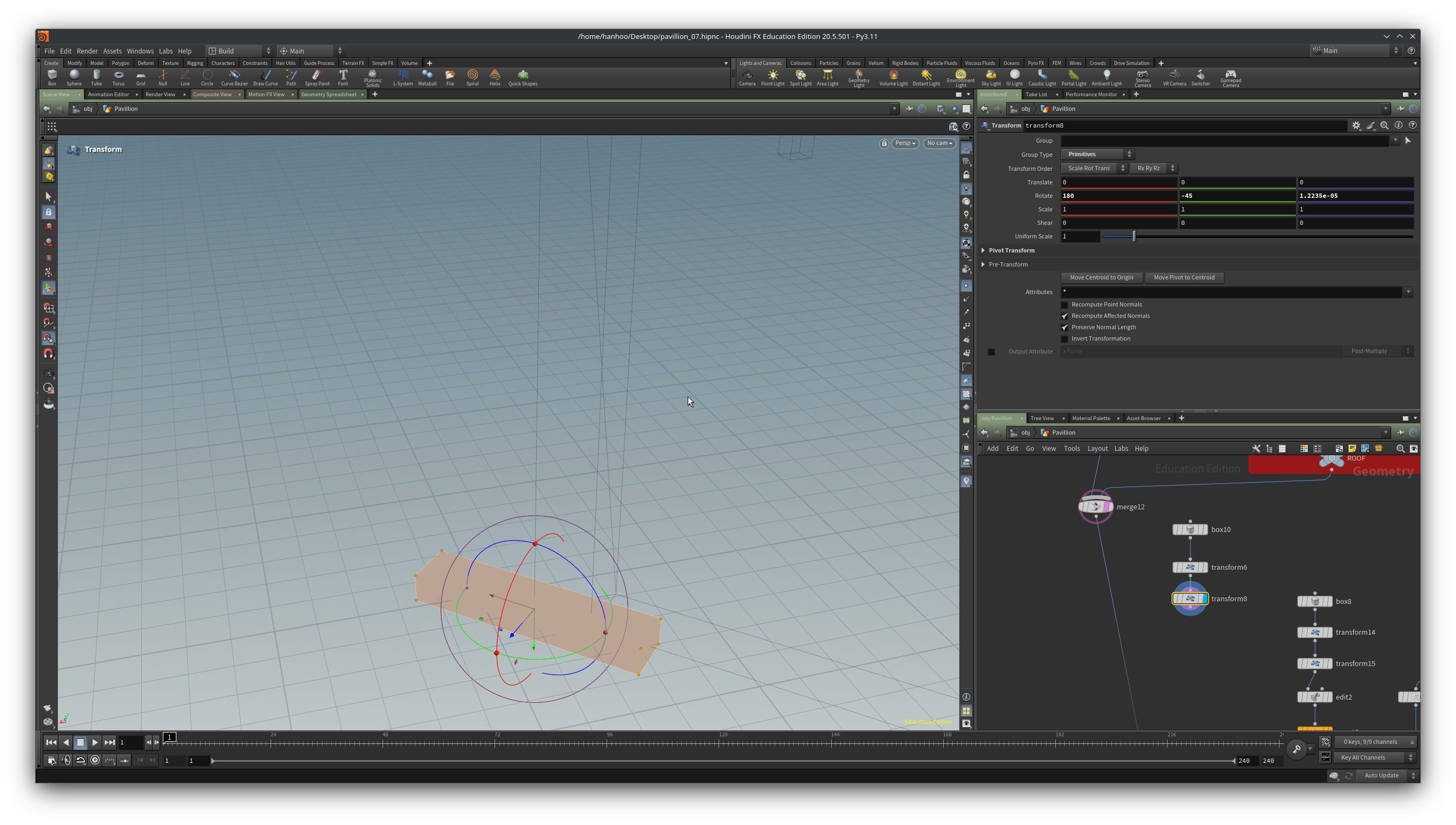
We see that the blue (z-axis) is now point in the same direction as the surface normal. But our box is still not in the correct orientation; the step should be rotated by 90 degrees to be properly orientated.
We can just change the Rotate channel to get the right orientation. In the example file it is easy, the rotation of the box happens to be -45 degrees, change it to 45 and we have the correct alignment. But if you have an angle of say 37.6453, then it becomes a bit more tedious to get the correct angle. The solution is simple though, just type + 90 after the value of the rotation and you are done.
If there is a very small value in the rotation around the z-axis, set it to 0.

We now have to translate the box so that it is not sticking through the wall of the exposition room.
Detach the handle by pressing ‘ and drag it to one of the corner points of the box. What would be a logical point to choose?
If the the handle is detached you see a little blu wireframe box around the center of the handle. Drag the handle to a new position and then reattach the handle again by pressing ‘. Drag the handle to the point on the outer wall at the entrance.


Finally! Our first step is correctly orientated and in the right position. Now we can start making copies of to create an actual stair.
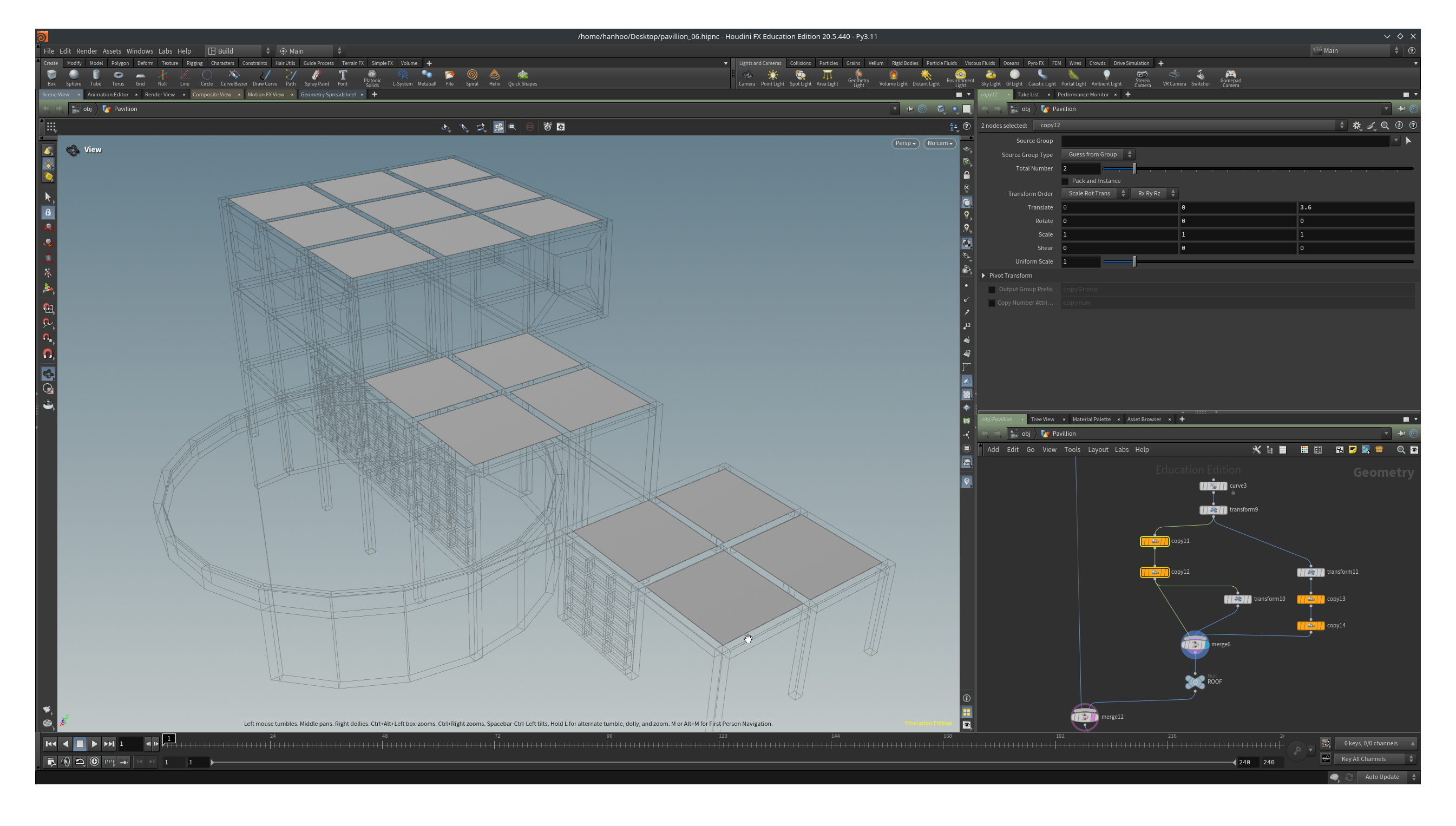
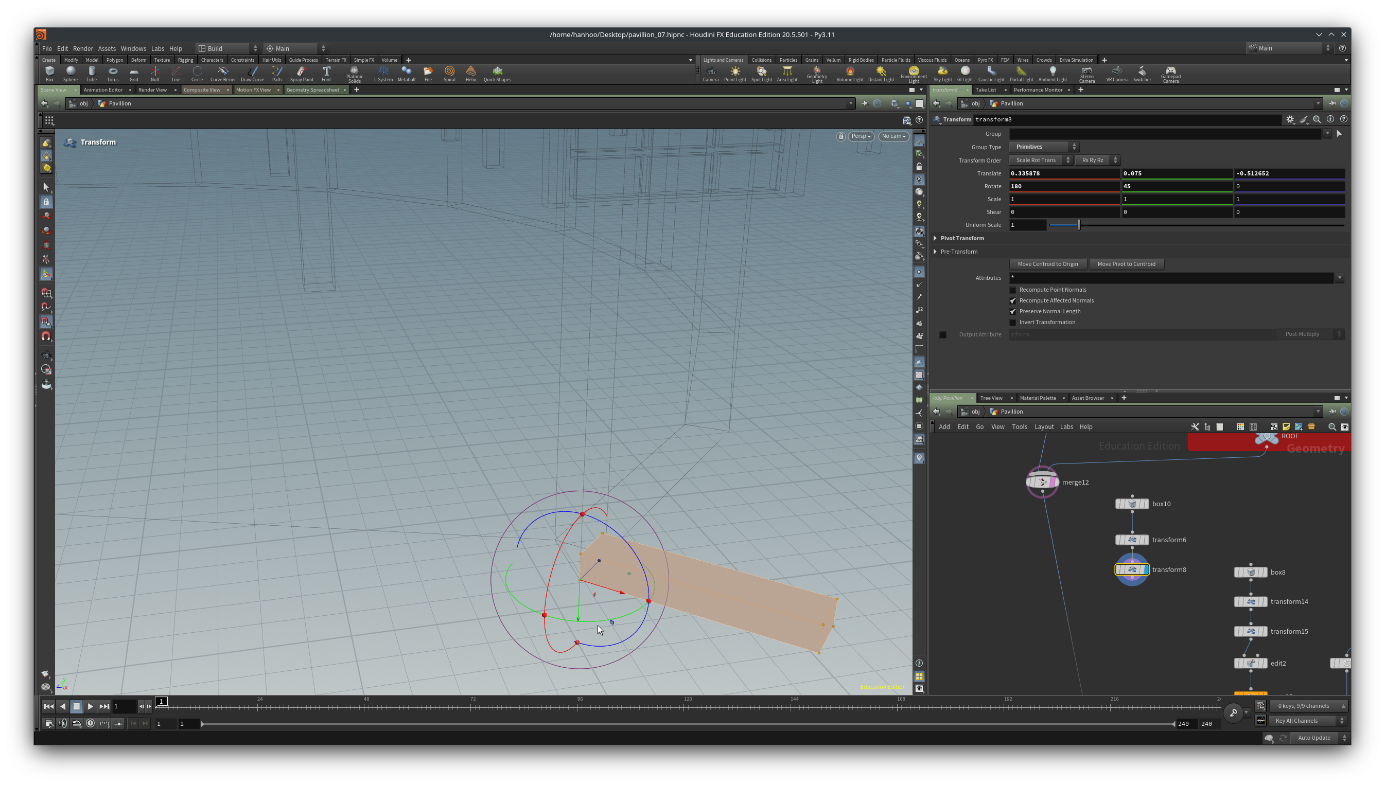
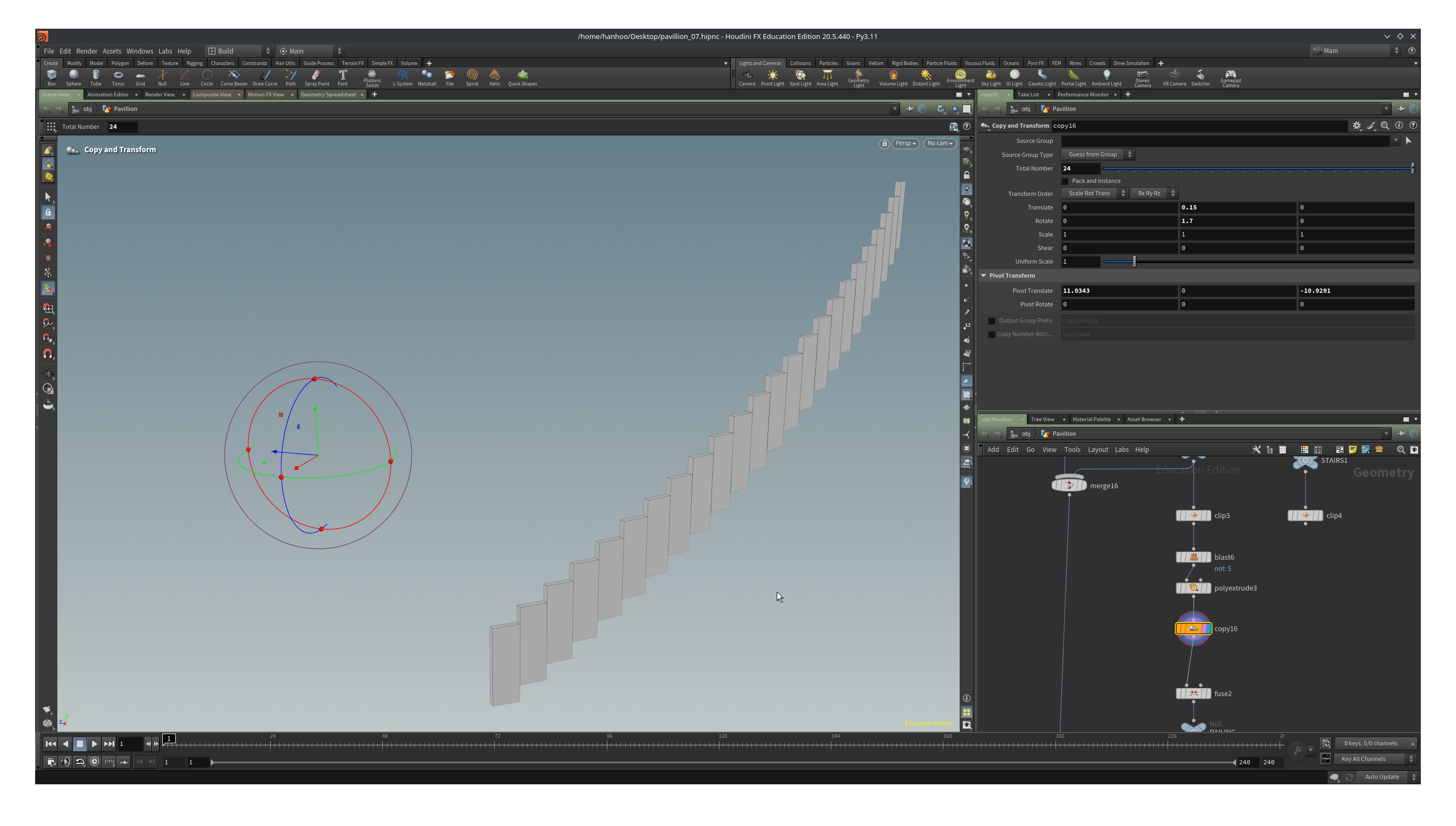
Our floor height is 3.6, our step height is 0.15. We need thus 24 steps for reaching the first floor. Lay down a Duplicate node and attach it to the last transform. Set the Total Number to 24. Every step should move 0.15 up so we can set Translate to 0, 0.15, 0. Since the stair is circular, wrapping around the exposition room, we need to rotate it around the Y-axis. By what degree though? Lets start with 2 degrees. Set Rotate to 0, 1, 0.
The result is defenitely not what we want!
The problem is that the origin of the rotation is 0, 0, 0 and that is not the center of the exposition room.
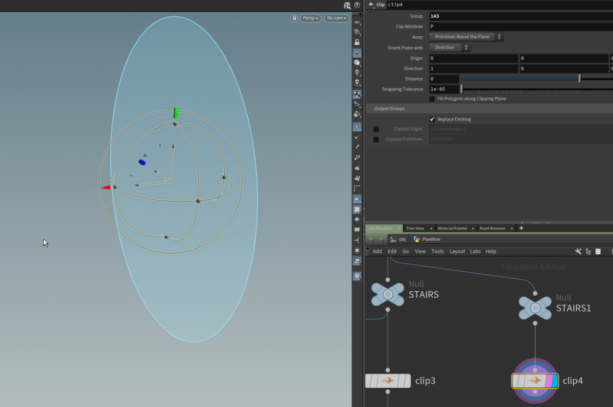
In the Duplicate node, click on the arrow left of Pivot Transform. Put the right coordinates in the Pivot Translate channel. The middle point of the exposition was on one of the corners of the columns of the grid.
Zoom out until you see the handle of the Duplicate node. Right click on the center of the handle and then select/tick Pivot Mode. The handle is now deattached from the Duplicate node and we can drag it to the same spot as we use for placing the cilinder for the exposition room. Right click and tick Pivot Mode again to reattach the handle. Our problem is solved.
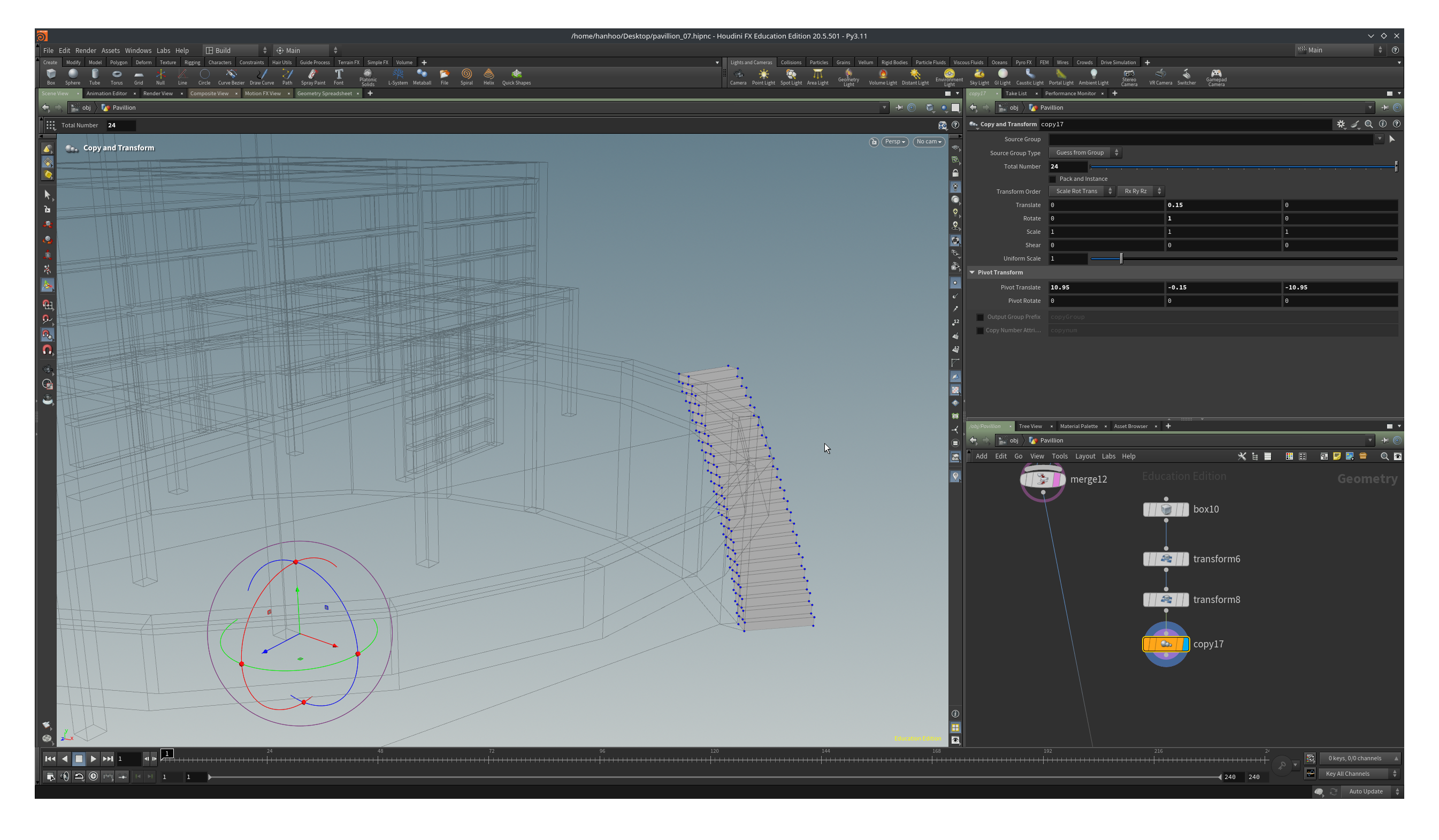
Change the rotation angle around Y in the D uplicate node to 1.7. The stairs should now have a minimal overlap on the outside radius.
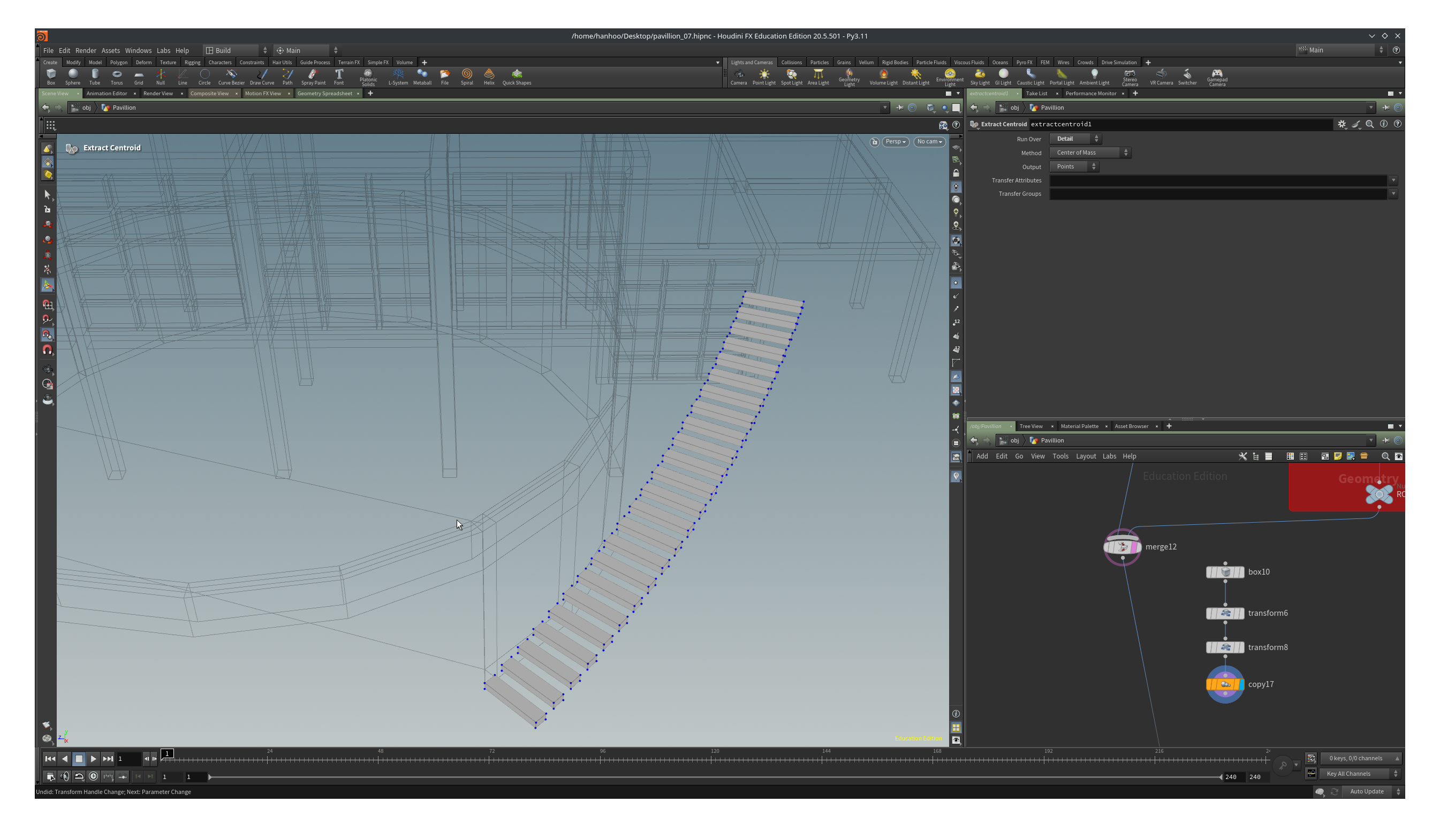
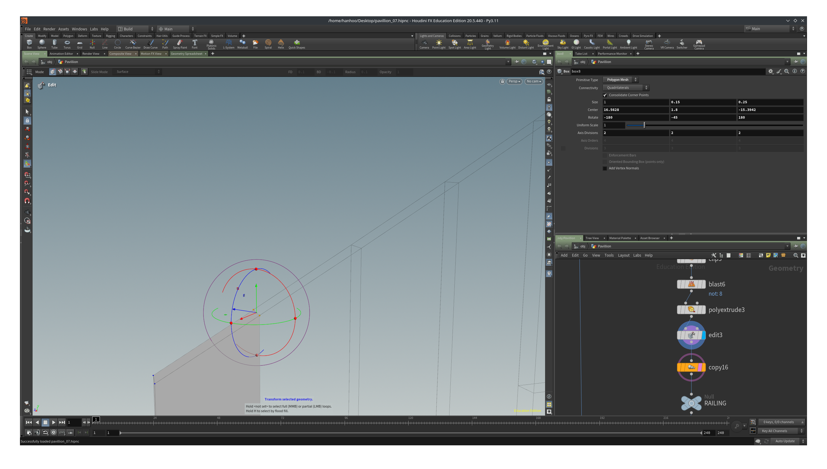
We can improve the stairs a bit by adjust the points on the first step. Insert an Edit node before the Duplicate node. Set the display flag on the Edit node and the template flag on the Duplicate node.
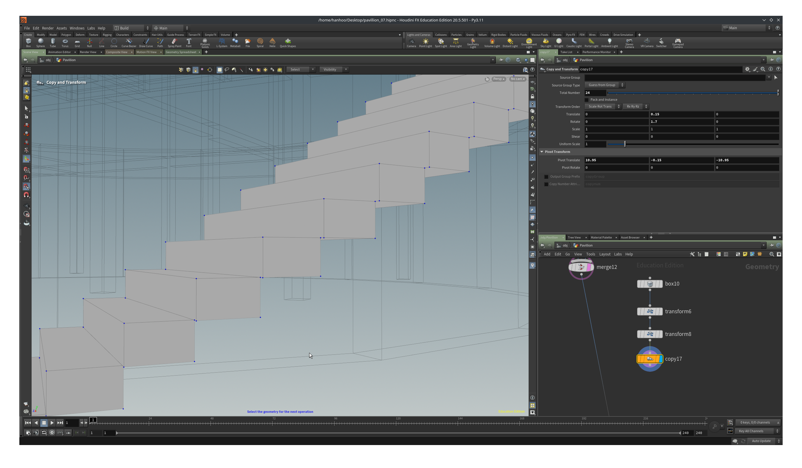
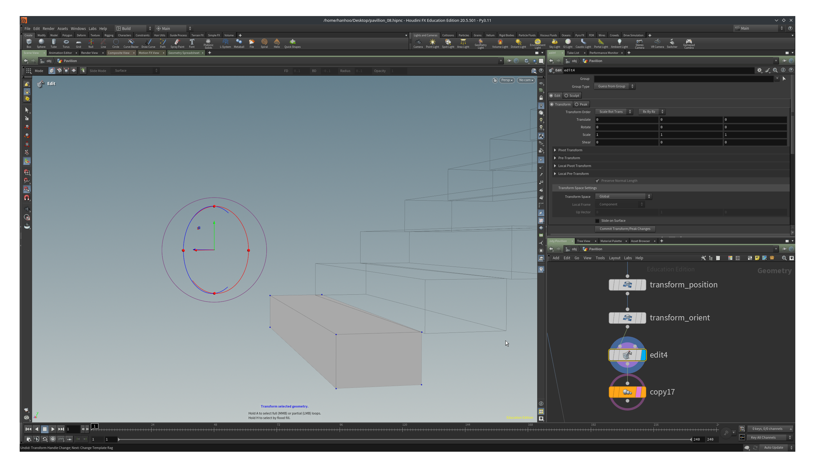
Turn on point snapping. We are going to move points from the “solid” step in such a way that they snap to the wireframe step. It should result in one smooth staircase.

Add a Fuse node after the duplicate. Now all points that are close together get snapped, making the back side of the stairs one smooth surface.
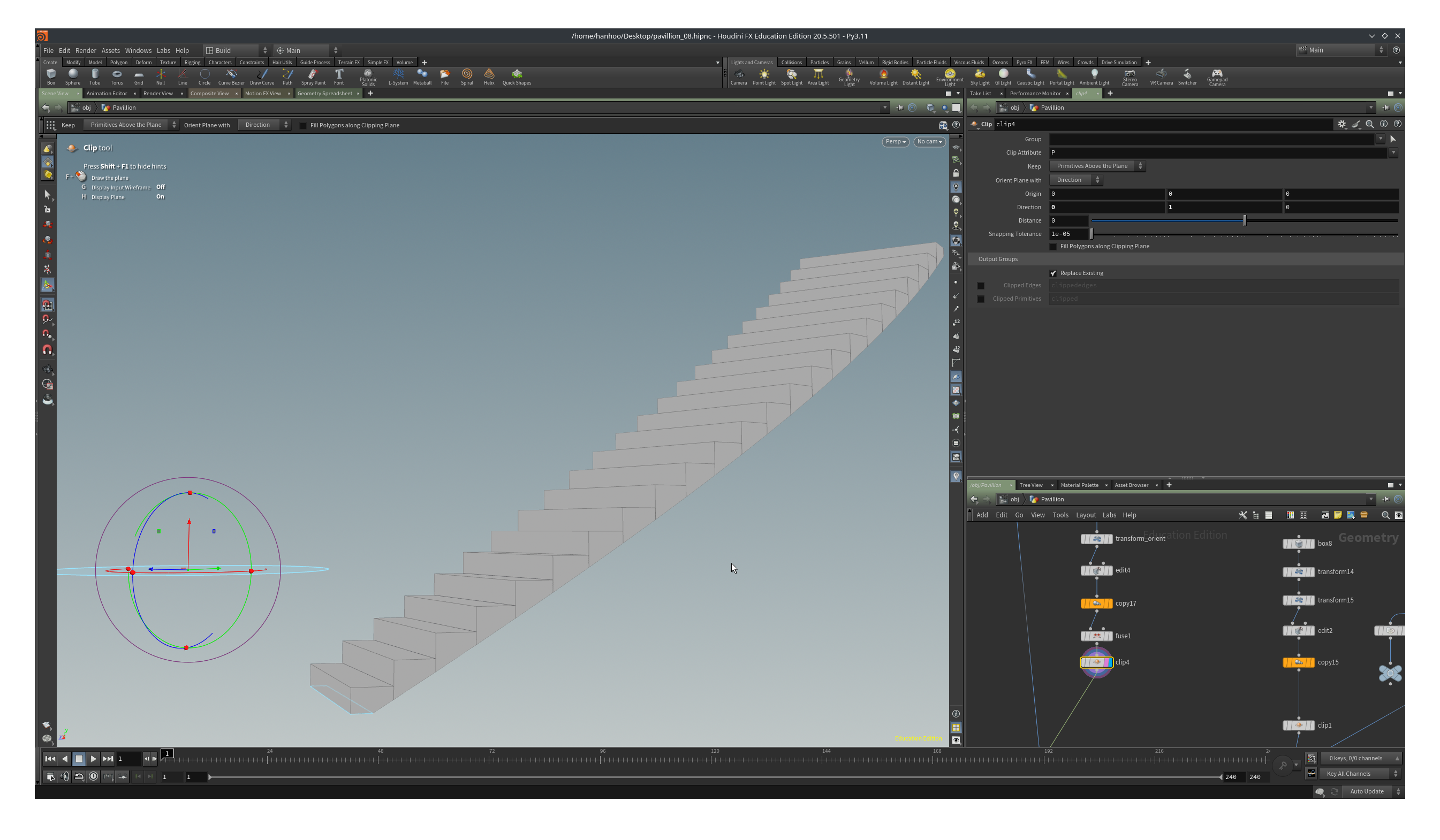
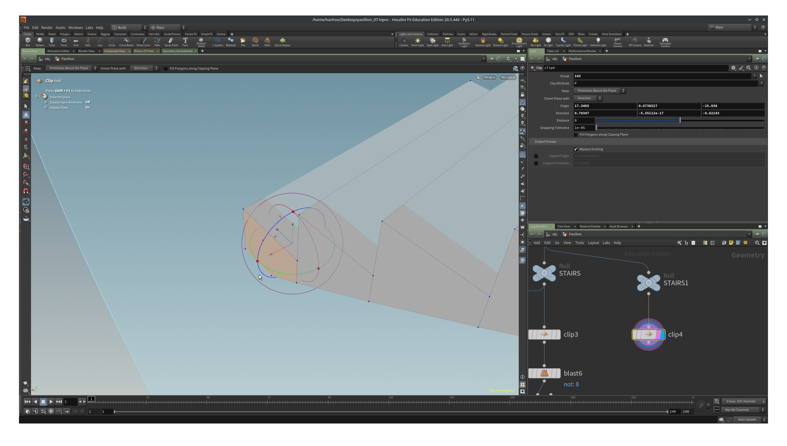
Add a Clip node and set Direction to 0, 1, 0. Our first step is stick through the ground. With the clip we delete everything below the clipping plane.
Add a Merge node and wire in the pavilion and the stairs.
The only thing left to do is adding a railing. We are going to place the railing on top of a step. We could try to draw a curve on the geometry but that is rather tricky due to lack of snapping options. To practice aligning handles, we are going to clip the first step. Attach a Clip Node after the last node of the stairs. By default it is located at 0,0,0 and pointing along the x-axis.
Right click on the center of the handle and then select Align -> Start orientation picking. Ctrl click on the red axis to make it the main axis for alignment.
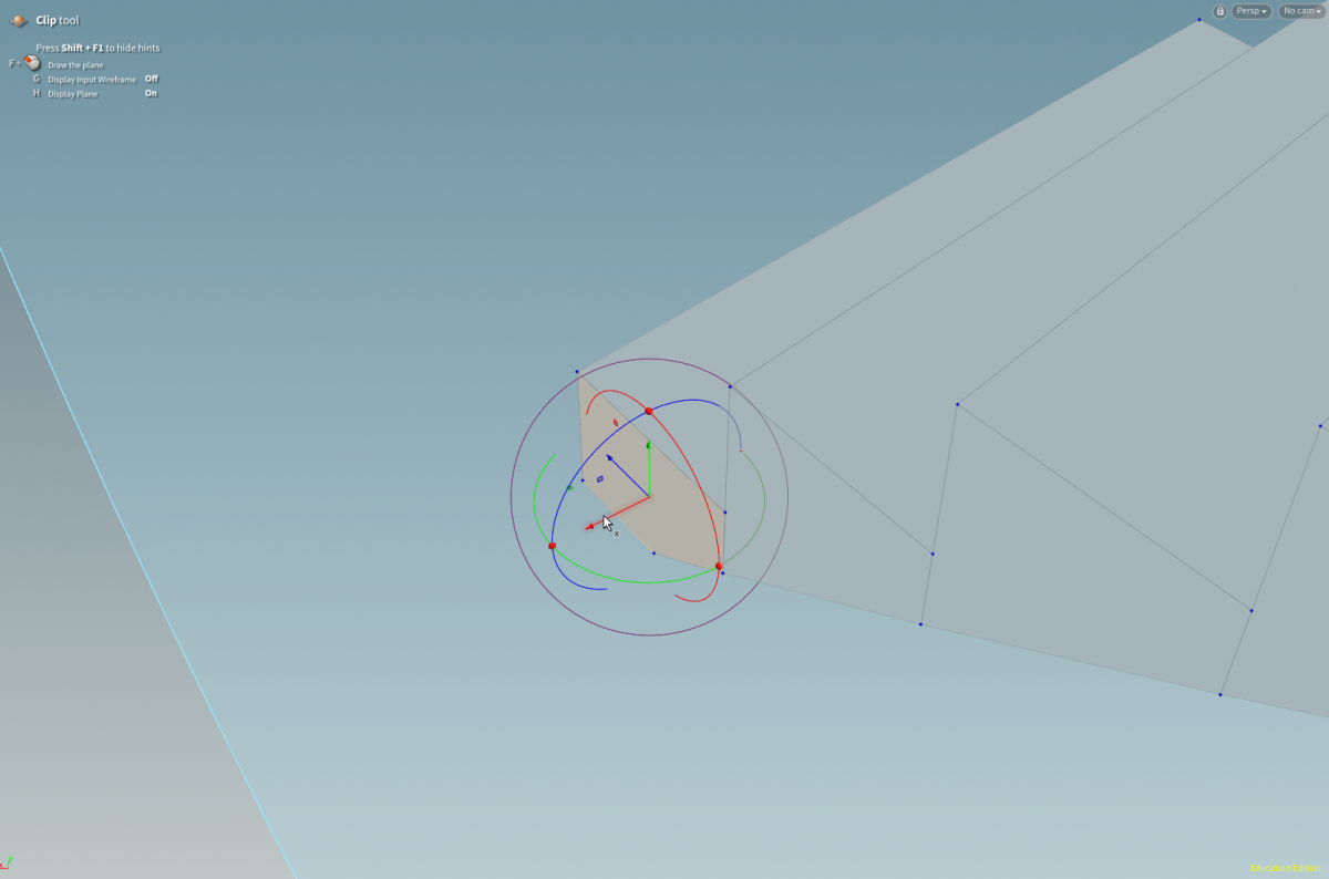
Move the mouse near the center of the side face of the chair till you see the brown square with the normal. Click and the Clipping plane will be parallel orientated with the primitive, drag it a bit back (or set Distance to -0.08) along the red axis and we will have the base of our railing.
Select the primitive that used to be the landing of the step (the horizontal primitive). Blast everything except this primitive (toggle Delete everything but selected).
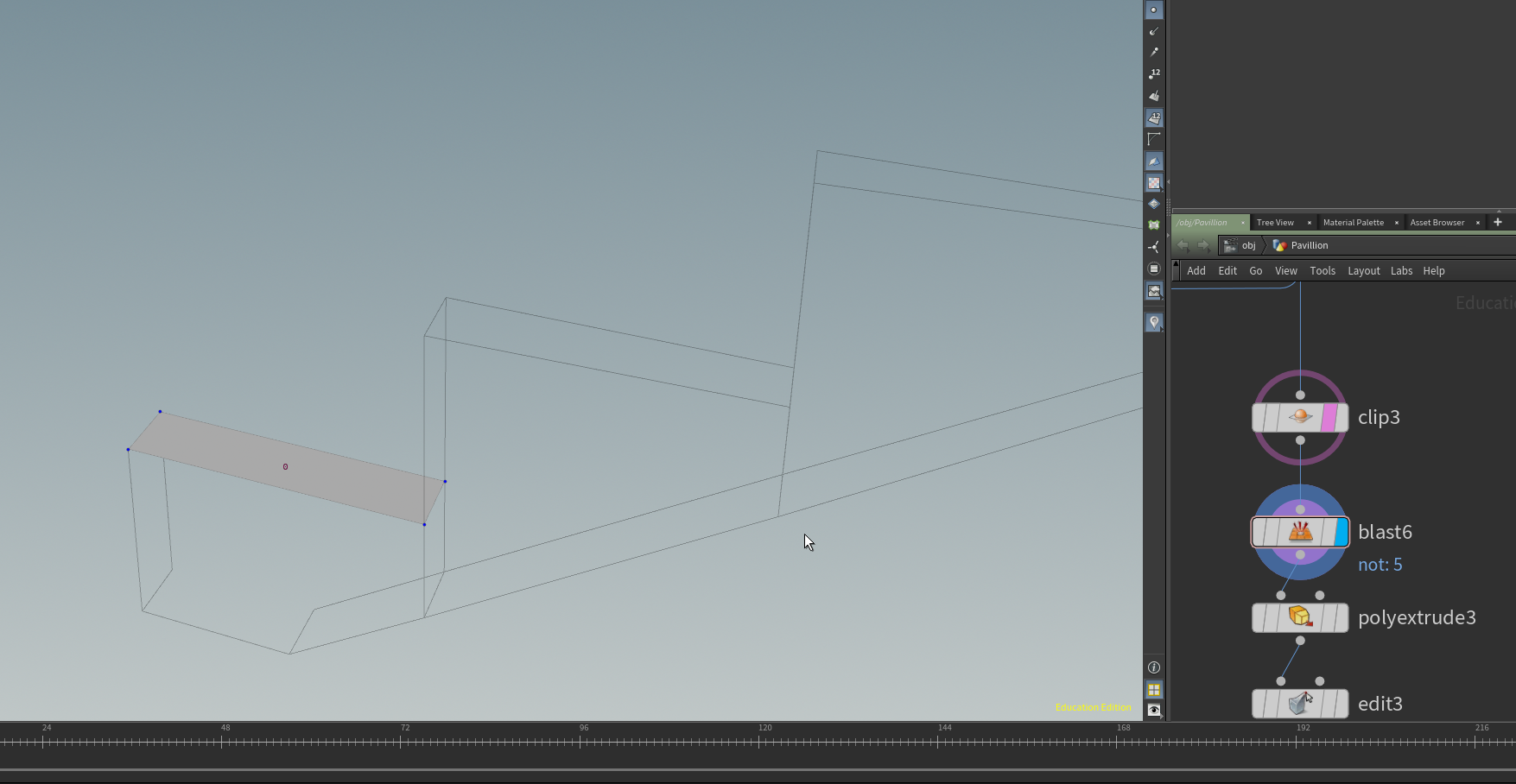
We Polyextrude the primitive 0.7 up.
Copy the Duplicate node we used for copying the steps and attach it to the extrude. We have now a our rainling resemble a small stairs. We want to have a smooth railing.
To make it a smooth we are going to do the trick like with smoothing the stairs. Put an Edit node before the Duplicate node and template the Duplicate node.
Turn on point snapping.
Select the two points closest to the next railing element in the view pane and then tab->edit. Move the points from the railing up until they snap the next railing element. If the edit handles are not aligned correctly, right click and select Align -> Align to world.
Attach a Fuse node after the Duplicate.
Merge in the railing with the rest of the pavillion and we are done.
We are still missing some walls. You can add them yourself, using the techniques from the previous chapter.
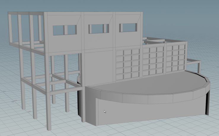
Below you can see the “finished” pavillion with the network.
Modeling an orthogonal pavillion in Houdini 6/6
The Pavillionlink copied
Write your feedback.
Write your feedback on "Modeling an orthogonal pavillion in Houdini"".
If you're providing a specific feedback to a part of the chapter, mention which part (text, image, or video) that you have specific feedback for."Thank your for your feedback.
Your feedback has been submitted successfully and is now awaiting review. We appreciate your input and will ensure it aligns with our guidelines before it’s published.