Honeybee Room set-up
-
Intro
-
Design
-
Geometry Creation Preparations
-
Organising the surfaces/meshes
-
Create HB faces
-
Connecting openings to walls
-
Creating the HB room
-
Creating the HB Model
-
Visualize & check the HB model
-
Conclusion
-
Useful Links
Information
| Primary software used | Honeybee |
| Course | BKB2WV3 – Digitale Ontwerpomgeving |
| Primary subject | Analysis & simulation |
| Secondary subject | Climate analysis |
| Level | Intermediate |
| Last updated | November 27, 2024 |
| Keywords |
Responsible
| Teachers | |
| Faculty |
Honeybee Room set-up 0/10
Honeybee Room set-up
The exercise aims to:
- Guide users through the process of conducting daylight and energy analysis using Honeybee.
- Highlight the important parameter for setting up the analysis geometry.
- Help students learn how to set-up a basic Honeybee room for simulations.
The techniques discussed in this example can later be applied to simulations for different design models or larger building groups.
Honeybee Room set-up 1/10
Designlink copied
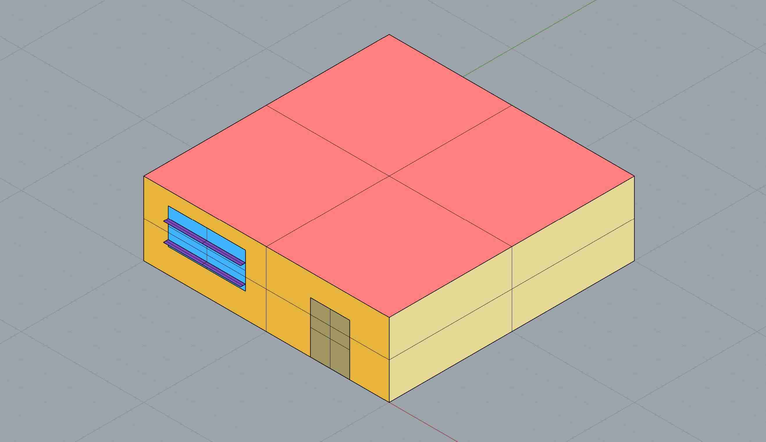
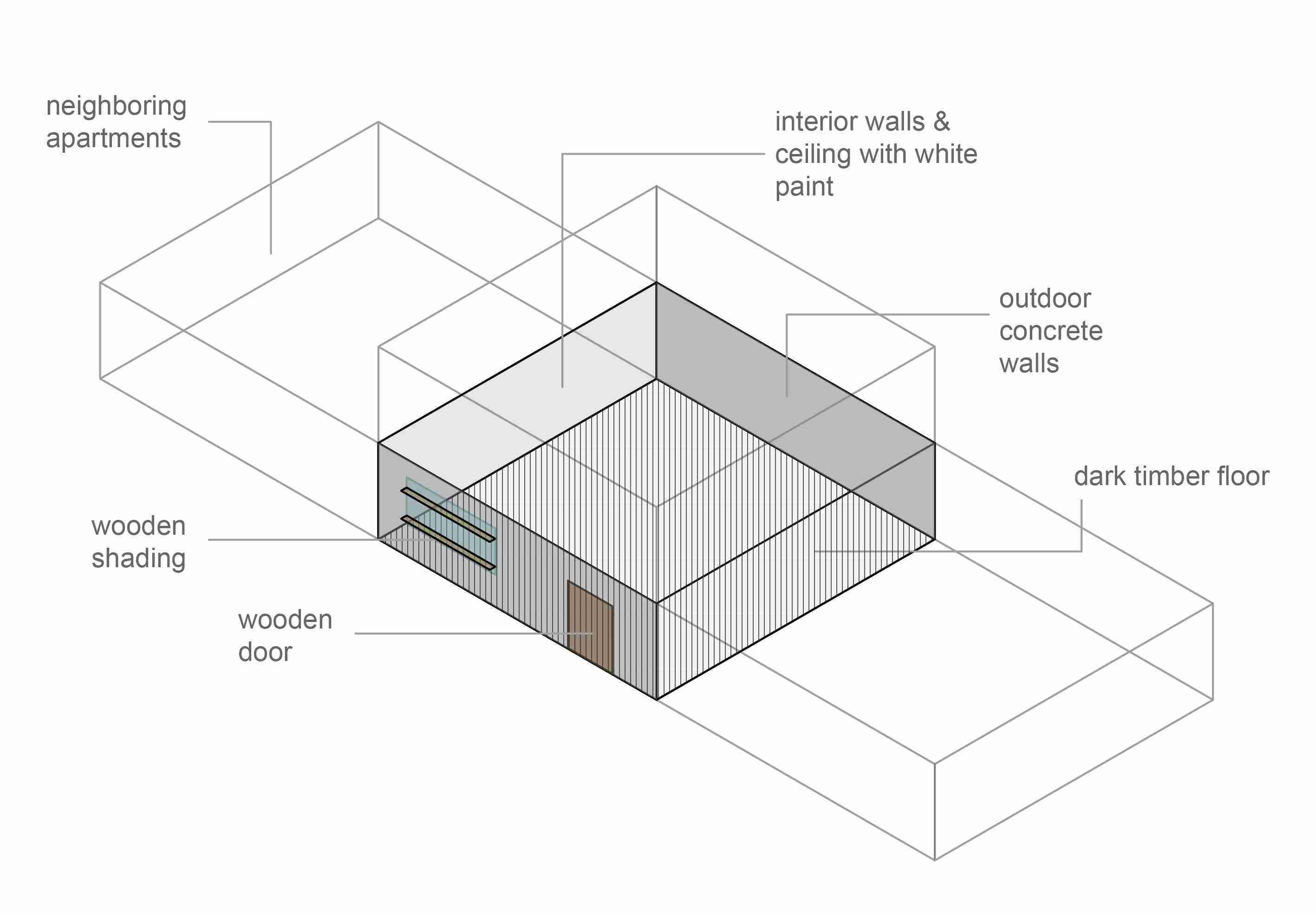
This example refers to a shoebox geometry and highlights all the important parameters both for setting up the analysis geometry, but also for running the different simulations. Let’s assume an apartment which is on the ground floor of a 2-storeys building. It has a rectangular plan of 10m*10m and it has a height of 3m. The apartment has an entrance from the road with an opaque wooden door and has also one operable window facing the street. The window is shaded with wooden horizontal louvres. On the left and right side there are adjacent apartments, but on the back side it is not neighboring any other apartment or building. The exterior walls are made of concrete in light grey color. The slabs are also made of concrete and they are painted in white color on the bottom side (ceiling). On the top part (floor), they are covered by timber in a darker color. The interior walls are made of plywood and covered also in white paint.
Abbreviations
HB = Honeybee Srf = surface component
Exercise file
In this tutorial, the detailed steps for the creation of a Honeybee room will be explained. You can download the GH-script with the room geometry used in this tutorial here as a starting point of this tutorial.
Honeybee Room set-up 2/10
Geometry Creation Preparationslink copied
In order to run an analysis through Honeybee, you should first convert the volumes that you have already created for your design into a Honeybee model. This involves importing the created geometry into separate Grasshopper components and organizing them appropriately, in order to have distinct components for walls, openings and shadings. Some important aspects of the openings surfaces creation need to be checked so that they do not obstruct the Honeybee room from running smoothly. Before moving on to using your geometry so as to create the Honeybee model for the analysis, you should pay attention to the following aspects.
Geometry separation
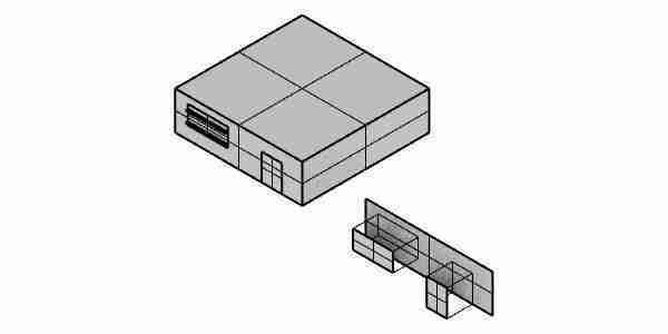
Make sure that each of the input Rhino Surfaces or Meshes is a unique entity and that they are not joined together into one big mesh or polysurface. This is important in order to be able to use them separately throughout the script (e.g. to assign different attributes). If you have a solid room/box as input geometry, Explode the created geometry in Rhino before importing the separate surfaces or you can use the Explode component in Grasshopper to separate them.
Surfaces without openings
Regarding the windows and doors, you will need to have the openings and the wall faces where the openings are applied to as separate entities. Specifically, the wall surfaces/meshes should always be full, without holes, as if there was no opening in them. Even if in your model has one façade consisting of only glazing, in Honeybee you will firstly use it as if it was a complete wall surface and the glazing will be applied to it in a later stage.
Margin error
In case you have openings (windows or doors) that reach to the boundaries of the respective walls, you will have to make them slightly smaller in order to have a small margin on the outer edges making sure that the whole opening surface is inside the wall.
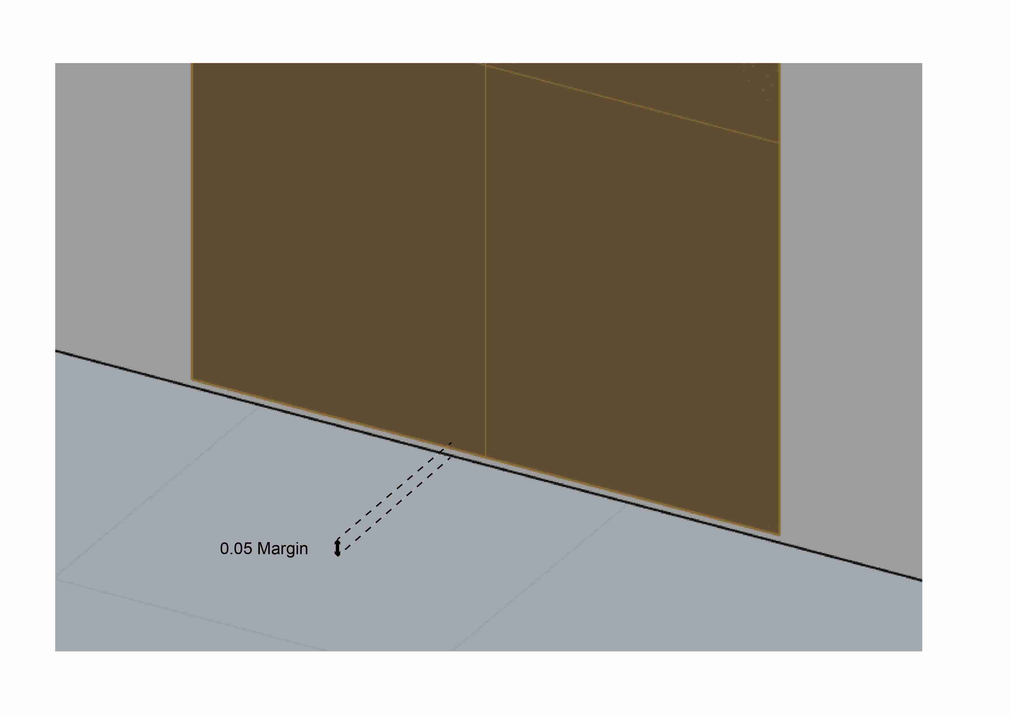
For example, in the example file, although the door normally starts from the bottom of the wall (+0.00) and ends at level +2.15, its height is made a bit smaller so that it still ends at level +2.15, but it starts from level +0.05. If in your model you have more than one edge reaching the wall boundaries, you should leave a margin in all the outer edges.
Closed volume

Although each surface/mesh should be separated, it is obligatory that all the input wall, floor and roof ceiling Surfaces or Meshes, if composed together, create a complete closed volume. Otherwise, running the daylight simulation will generate light leaks and result in false results. This is why you will see errors in your script and the Honeybee model will fail to be created.
Honeybee Room set-up 3/10
Organising the surfaces/mesheslink copied
In Grasshopper, all the surfaces/meshes created in the Rhino model need to be grouped based on their type (e.g. exterior or interior, walls that have windows or not). Therefore, create a sperate surface/mesh component the following groups:
|
Category |
Description |
|
|
A |
Interior wall faces |
(Inner divisions and walls that are adjacent to neighbouring building) |
|
B |
Exterior wall faces |
(All the complete wall faces, even the ones having a door/window. Be careful that in the latter case you should assign them full and without the opening holes!) |
|
C |
Floor faces |
|
|
D |
Roof ceiling faces |
|
|
E |
Window faces |
(Only the window surfaces and not the complete wall!) |
|
F |
Door faces |
(Only the door surfaces and not the complete wall!) |
|
G |
Shadings |
|
After you created a Surface component change the name of the surface component to the name of the group. If you have the setting of view on icons, then you can change the view setting of a component to ‘Always draw name’. By doing this, the script will stay organised, and the separate groups of surfaces will be found back easily.
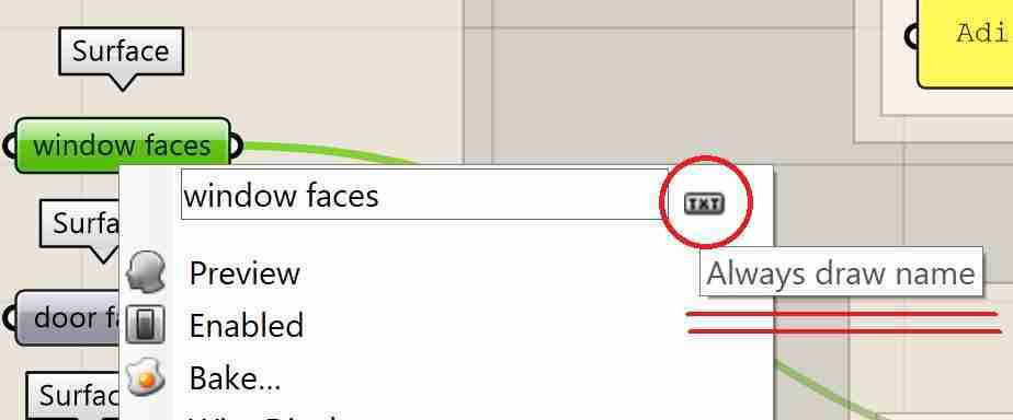
- Create 7 surface components
- Change component name
- Change the component view to ‘Always draw name’
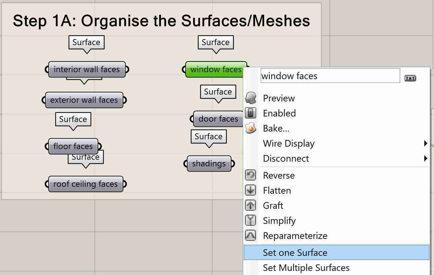
After you created a surface component for each group, import the geometry from Rhino using the RMB to Set one/multiple Surface/Mesh.
- Import surface type of your model to corresponding category.
Honeybee Room set-up 4/10
Create HB faceslink copied
The second step to create the HB model is to first create all separate HB faces. In order to do that, all group categories created in the previous step need to be used as inputs in the appropriate components. These components might be HB face, HB Aperture, HB Shade or HB Door components according to the category.
HB solid faces
For each of the aforementioned A-D categories (Walls / Roof / Floor / Ceilings) create a HB face and add information of the surface type accordingly. Two information streams need to be added to the surface, namely: the face type and the boundary condition. For boundary condition you can choose between:
|
Boundary condition |
Description |
|
|
a |
Ground |
for a floor which is placed right above the ground |
|
b |
Outdoors |
for exterior walls and roofs |
|
c |
Adiabatic |
for interior walls and intermediate floors |
For each surface type that consists in your design, create a HB face component and define the face type and boundary condition. Then connect all the surfaces that correspond with the face type.
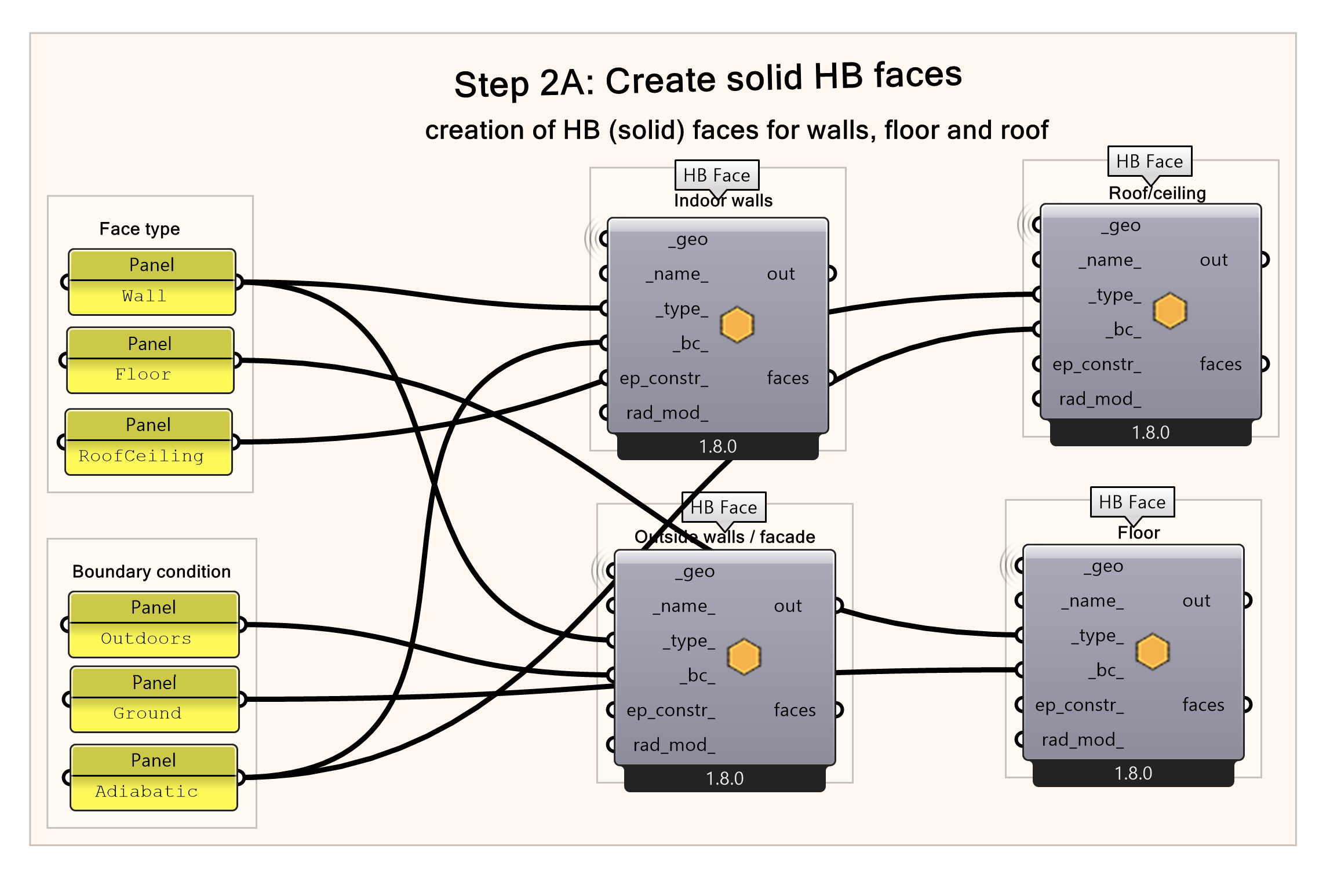
- Add a HB face component for each surface type.
- Connect panel with the type description to ‘_type_’.
- Connect panel with the boundary condition description to ‘_bc_’ input.
- Connect the respective Surface component created previously to _geo input of the HB face.
Note: Make sure that you use the names exactly as referred to on the component for both the face type and boundary conditions. For face type choose between: Wall, RoofCeiling, Floor. For boundary condition you can choose between Ground, Outdoors, Adiabatic.
HB Window faces
For category E (only window faces) an HB aperture components is used. For window extra information need to be added about operable windows. Write “True” for operable windows, otherwise write “False” in a panel. (In case you have both operable and inoperable windows you need to create 2 different HB Aperture components). Additionally, the wall thickness will be added οn the perimeter of the aperture, accounting as additional shading elements. For this tutorial wall thickness of 0.3 meter is used. If you want to check if your window is modelled correctly you can use the HB_Visualize_All component.
- Add an HB aperture.
- Connect the “Window faces” Surface component as input to ‘_geo’.
- Connect panel with operable status to input of ‘operable_’ by Params » Input » Panel
- Add wall shade to window.
- Connect the ‘apertures’ result from the HB Apertures component as input to ‘_hb_objs’.
- Connect slider with wall thickness to _depth.
- Connect panel with indoor/outdoor description to input of ”indoor_’.
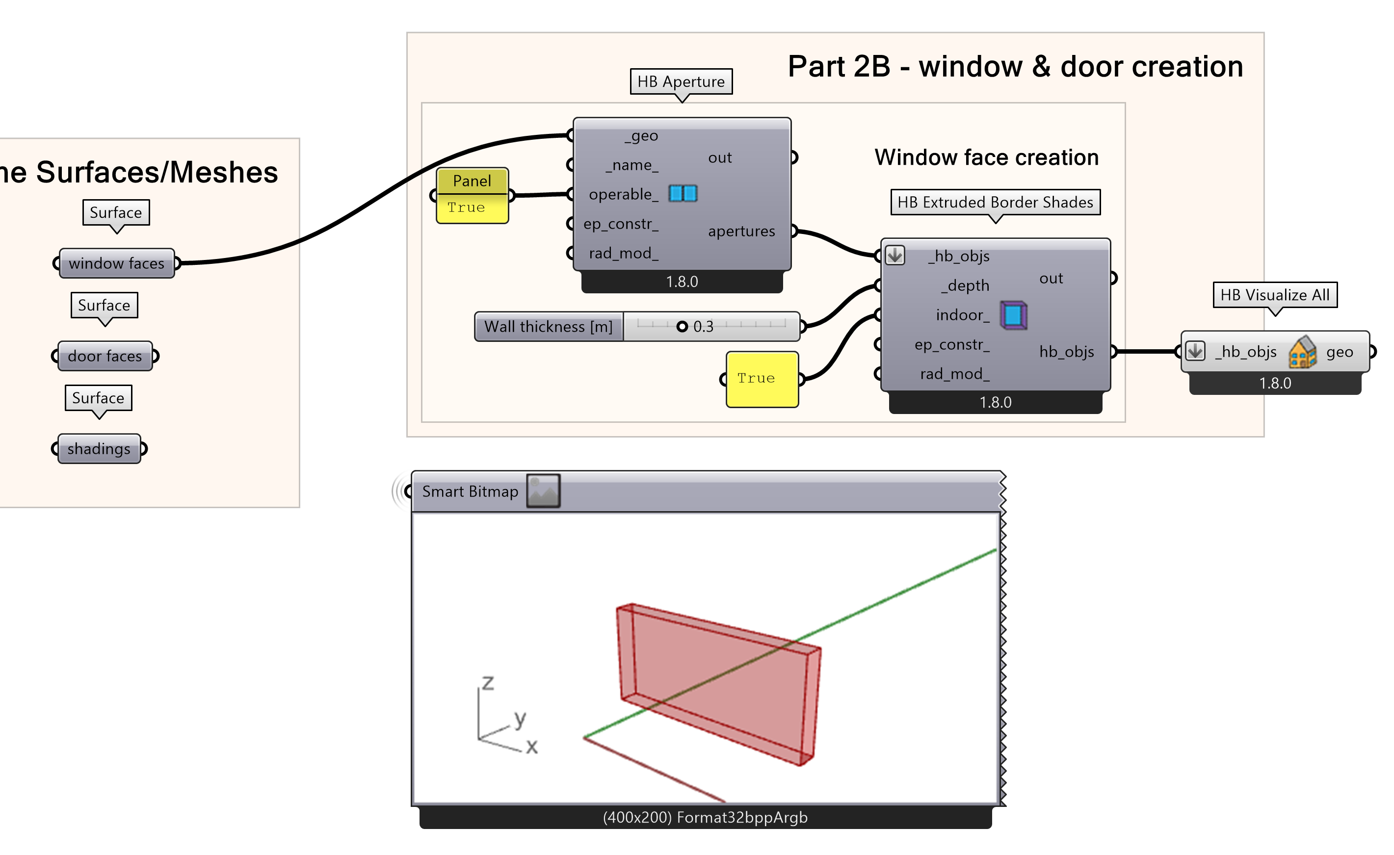
Note: Put the “true” / “false” description of the indoor/outdoor description panel so that the extrusion happens towards the interior as it represents the wall thickness.
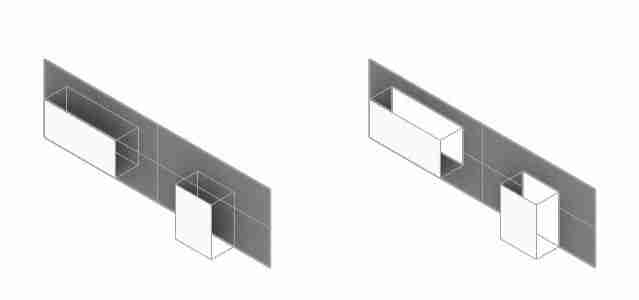
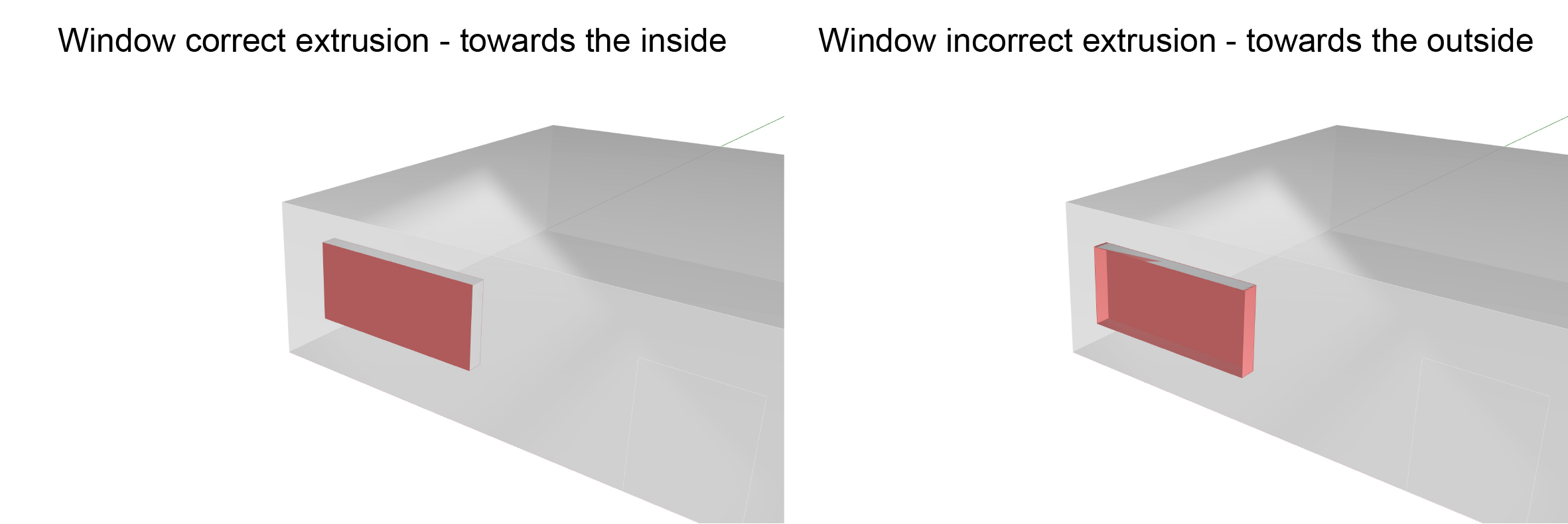
The “true” / “false” description indicates on which side, inside or outside of the room, the wall will be extruded. The extrusion of the wall face indicates the depth of the wall where the window opening is, and therefore, it influences the results of the sunlight analysis later on. In the images below, you can see the difference between the 2 settings and how the HB room is composed if you use the “true” indication for the extrusion on the top image or the “false” indication on the bottom image. The “false” indication leads to a result which is incorrect, since the wall depth now looks like a shading instead of what it should be. Therefore, always be careful with the setting you choose. Note: be aware that the true/false setting can be different if you window surface is flipped, therefore, you should always check the border direction.
HB Door faces
For category F (only door faces) an HB door components is used. For doors extra information need to be added about if the door contains glass. In a panel, write “True” for transparent doors and “False” for a solid door.
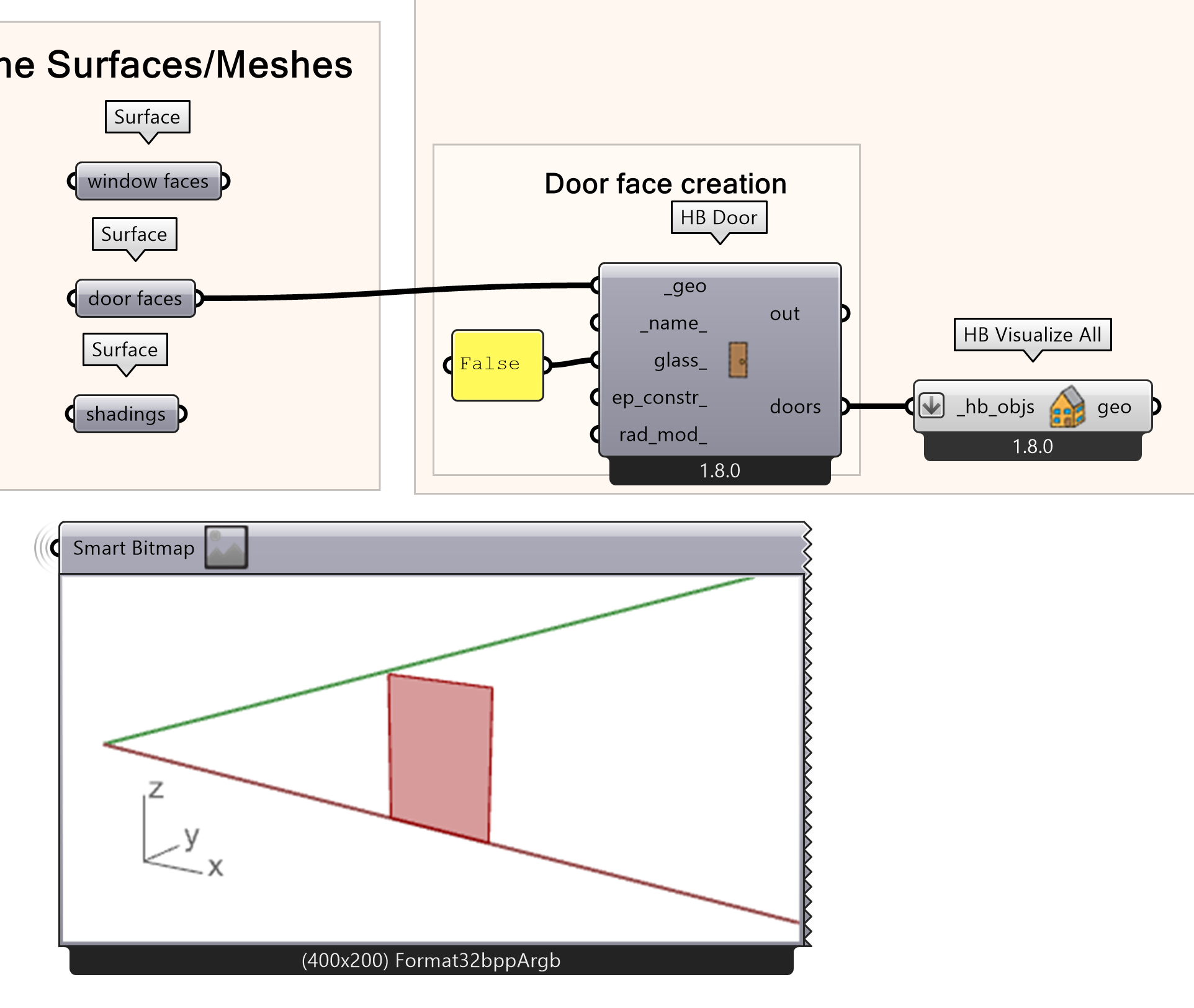
- Create a Honeybee Door.
- Connect the “Door faces” Surface component as a ‘_geo’
- In the ‘glass_’ input, connect a panel with the true/false description of transparent door.
Note: In case that you also have interior doors, you should create a separate component for them.
HB shade faces
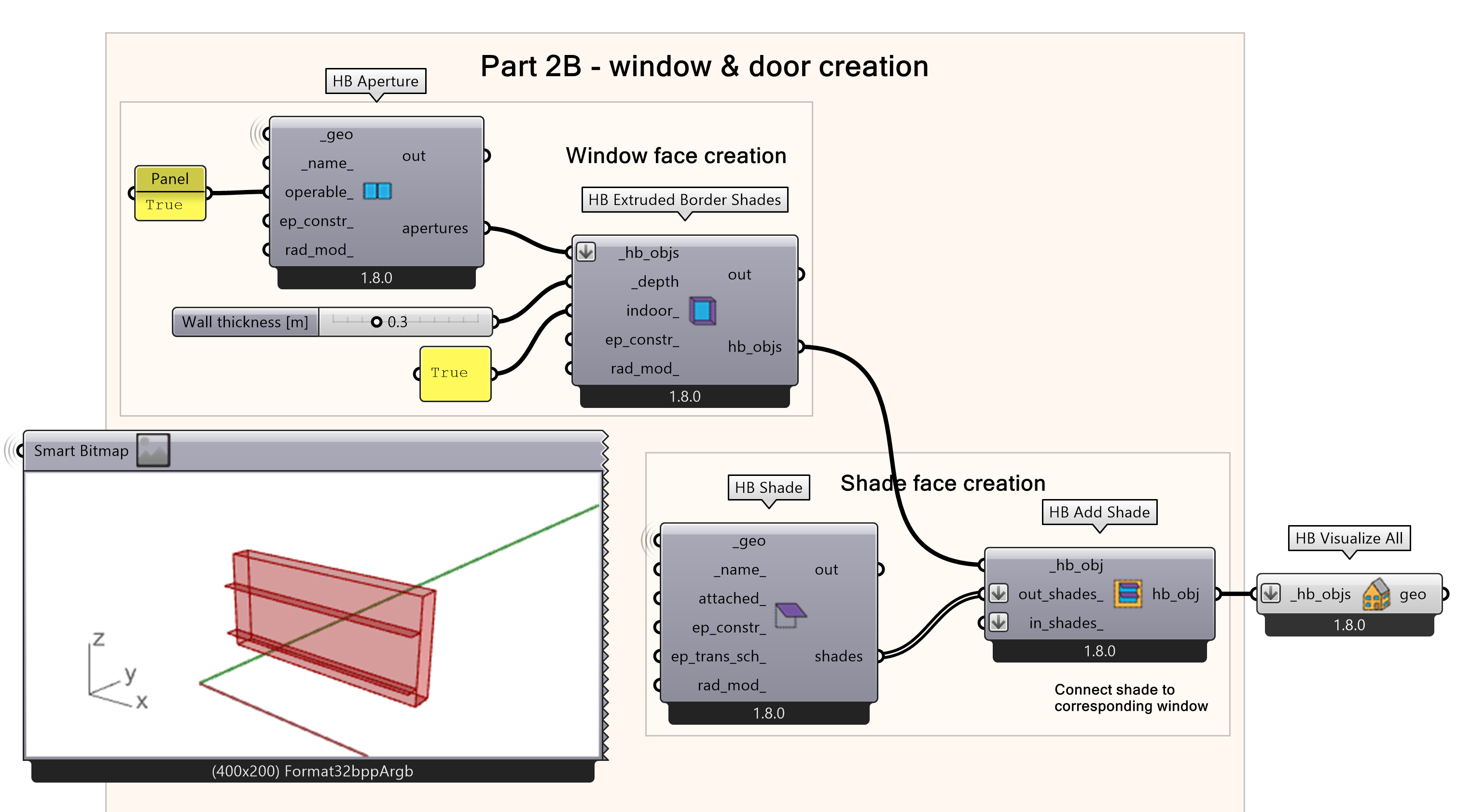
For category G (Shades) an HB shade and HB add shade component are needed. If your window has shading then first you need to create a HB shading face and then you need to connect the shading with the corresponding opening(s).
- Create shading faces.
- Connect the “Shadings” Srf component as a ‘_geo’
- Create a Honeybee Add Shad component.
- Connect shade to opening(s) by connecting the ‘_hb_obj’ output from the HB Extrude Border shades to the ‘_hb_obj’ input from HB Add Shade
- Connect the ‘shades’ result of the HB Shade component in the ‘out_shades_’ or ‘in_shades’ input of HB Add Shade for exterior or interior shades respectively.
Honeybee Room set-up 5/10
Connecting openings to wallslink copied
Before composing the room, an important step is to create an HB subface where all openings (window & shades, door) will be assigned onto the correct wall face. Afterwards, the HB room can be created using the faces that compose it. In this step a lot of possible errors can occur if a small mistake is made somewhere or a component is not exactly constructed as per the HB request.
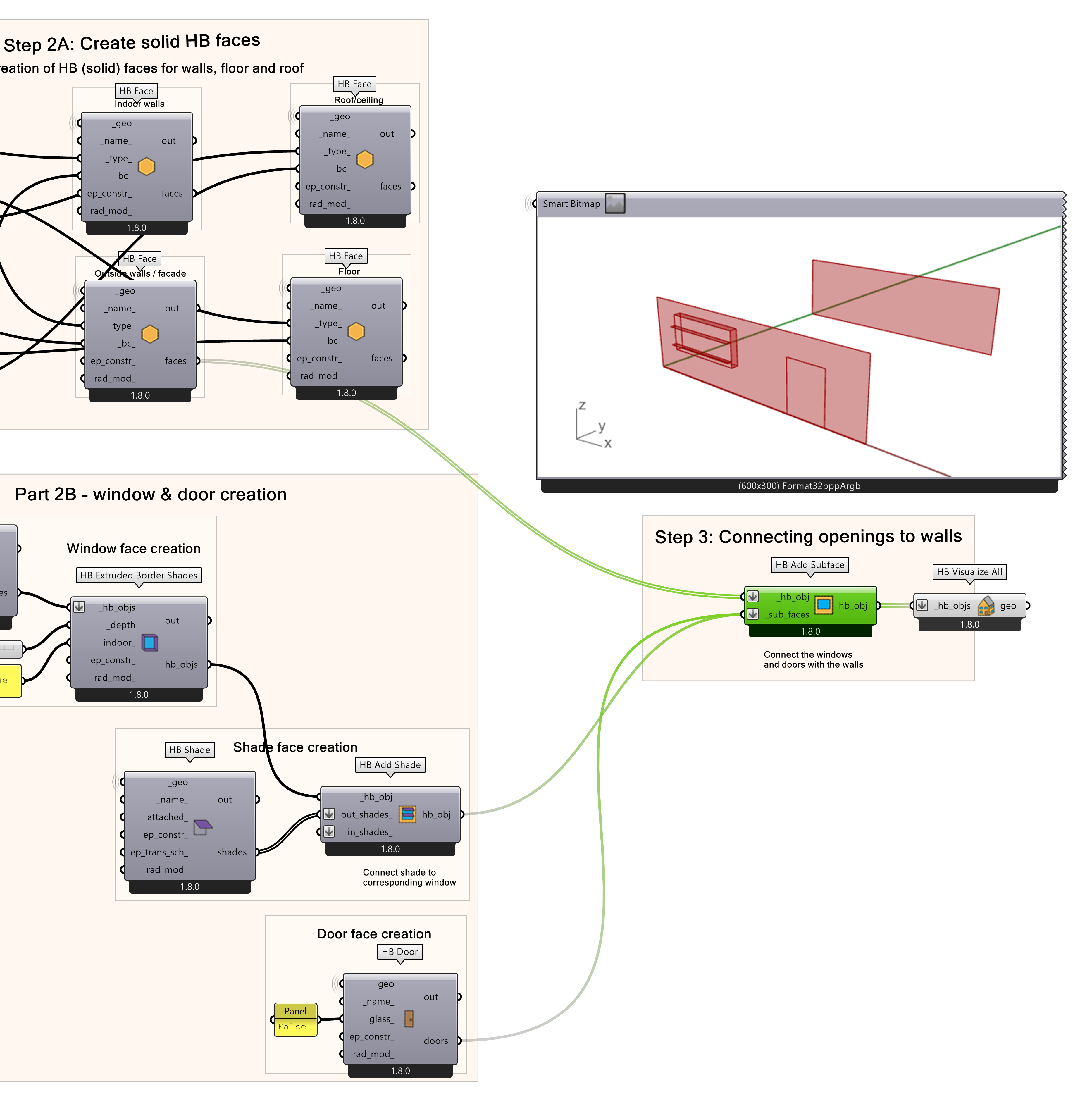
Now that the opening HB faces are constructed, they can be assigned to their respective walls HB faces. To do so a HB Add Surface component is created and the wall and openings are inputted.
- Create a add surface component.
- In the ‘_hb_obj’ input, connect the ‘faces’ result of the HB face component related to the ‘Exterior wall faces’.
- In the ‘_sub_faces’ input, connect all the ‘hb_obj’ or ‘doors’ result of the HB Add Shade or HB Door component respectively.
Note: If your model does not have shading use the ‘hb_obj’ result of the HB Extruded Border Shades as input for the ‘_sub_faces’ in the HB Add surface component. If shades are applied to an aperture, you should connect to the ‘_sub_faces’ input, the ‘hb_obj’ result of the HB Add Shade component that includes both the apertures and the shading.
Possible errors while using HB Add Subface
In case you run into a problem check the following 4 most common errors that occur while using HB Add Subface. A very frequent error message that may show up when connecting the inputs to the ‘HB Add Subface’ component is that:
“The following subfaces were not matched with any Parent face.”
If this is the case:
- Check that for each opening that you have connected as an input on the ‘_sub_faces’, there is the respective FULL wall surface connected as an input on the ‘_hb_obj’ input.
- Make sure that both ‘_hb_obj’ input and ‘_sub_faces’ are flattened (right click on the input » Flatten).
- In case you have openings (windows or doors) that reach to the boundaries of the respective walls, make sure you have a small margin on the outer edges as the whole opening surface needs to be inside the wall.
- If the other steps still do not solve the problem, it may be the case that there is a slight deviation between the wall plane and the window reference plane. (Maybe it is so small that you do not realize.) You can project the opening surface to its respective wall surface and connect the ‘Geometry’ result in the HB Aperture or HB Door component. In this case, make sure that you apply on the ‘Plane’ input of the Project component only the wall where you want the opening to be projected!
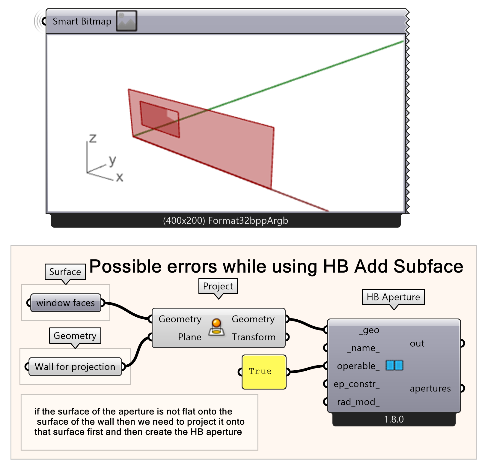
- Project opening on wall.
- Input the respective wall and opening(s) in the Project component
- Use projection geometry as input for _geo in the HB Aperture component
Honeybee Room set-up 6/10
Creating the HB roomlink copied
Now, the HB room will be created from the HB faces that compose it. To do so, a HB Room component is used where all the created HB faces or HB Add subface objects are inputted. In our example the result of the ‘hb_obj’ from HB Add subface contains all the Exterior walls connected with their respective openings and shades. In case you have created a different HB Add Subface component for applying interior doors, you should connect that to the HB Room component and not the ‘faces’ from the HB Face component related to interior walls. In this step also a characteristic name for the room you are creating can be given.
- Create a Honeybee Room.
- In the ‘_faces’ input, connect the ‘faces’ result of the HB Face components related to the Interior walls, Floor and Roof/ceiling. And add the ‘hb_obj’ result of the HB Add Subfaces
- Connect a panel with a room name.
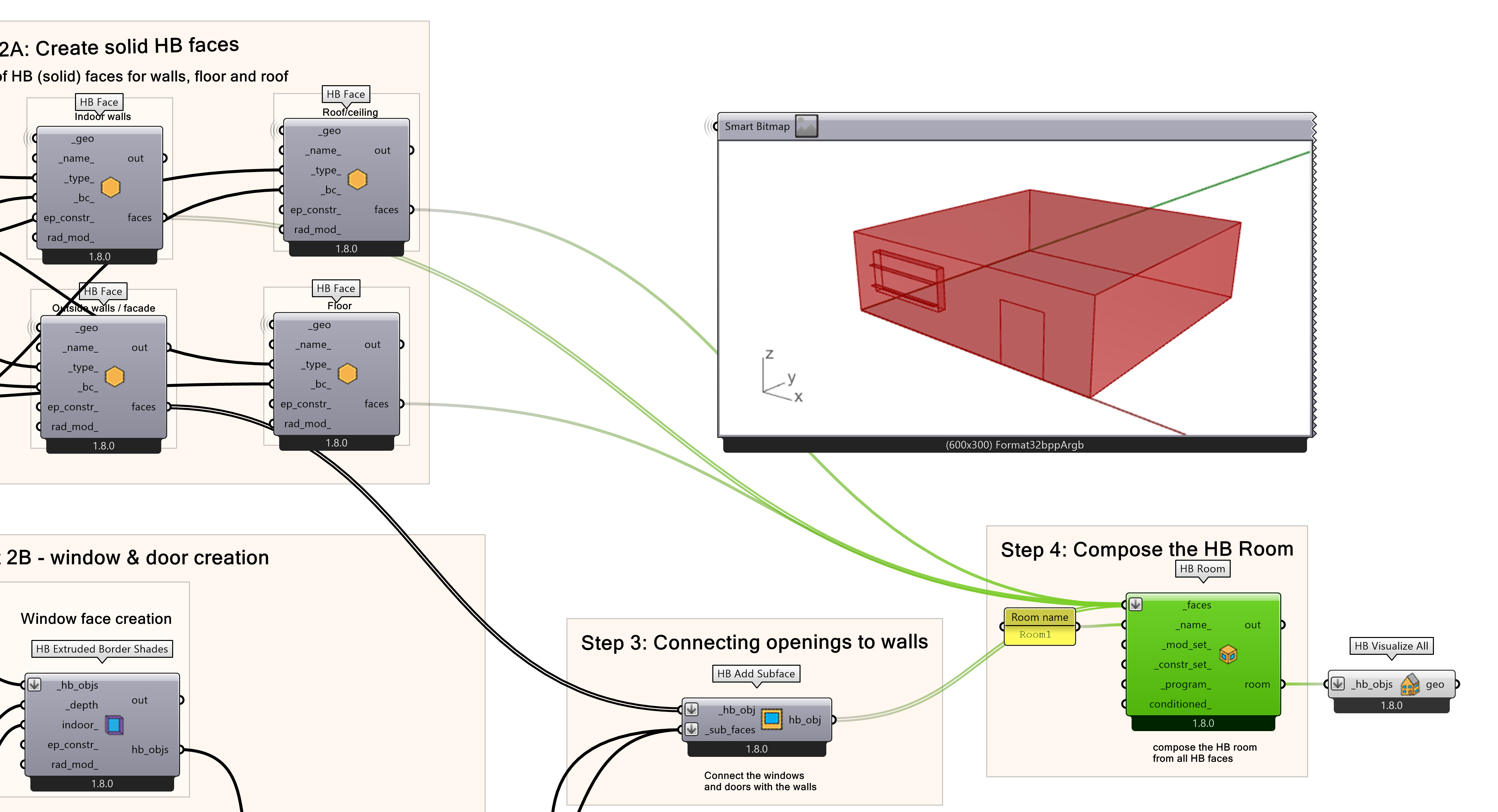
Possible errors while creating a HB room
While creating a HB Room several errors can occur. Be aware of the following points:
- Do NOT connect as input the ‘apertures’ result (from the initial HB Apertures component) or the ‘hb_obj’ result of the HB Extruded Border Shades component as input for the HB Room component.
- In case you have interior doors, you should create another HB Add Subface component, where you will apply them to the interior wall faces.
- Make sure that every face is connected only once to the HB Room component! Do not connect again the Exterior Wall faces, Window or Door faces or Shadings. They are all included in the hb_obj from the HB Add Subface command!
- Make sure that no face is missing and the Honeybee room you are creating is a closed volume. The HB Room command is going to create an error if the room faces in total are not creating a closed volume.
Honeybee Room set-up 7/10
Creating the HB Modellink copied
When the HB Room is created the Grasshopper script is ready to create the complete HB Model. The HB Model components is used, whereas the HB Room output ‘room’ serves as input. To check the validity of the model you can run a HB Validate Model component. This can prevent errors during next steps while setting up a simulation. To see the result of the check add a panel to the report and examine the report.
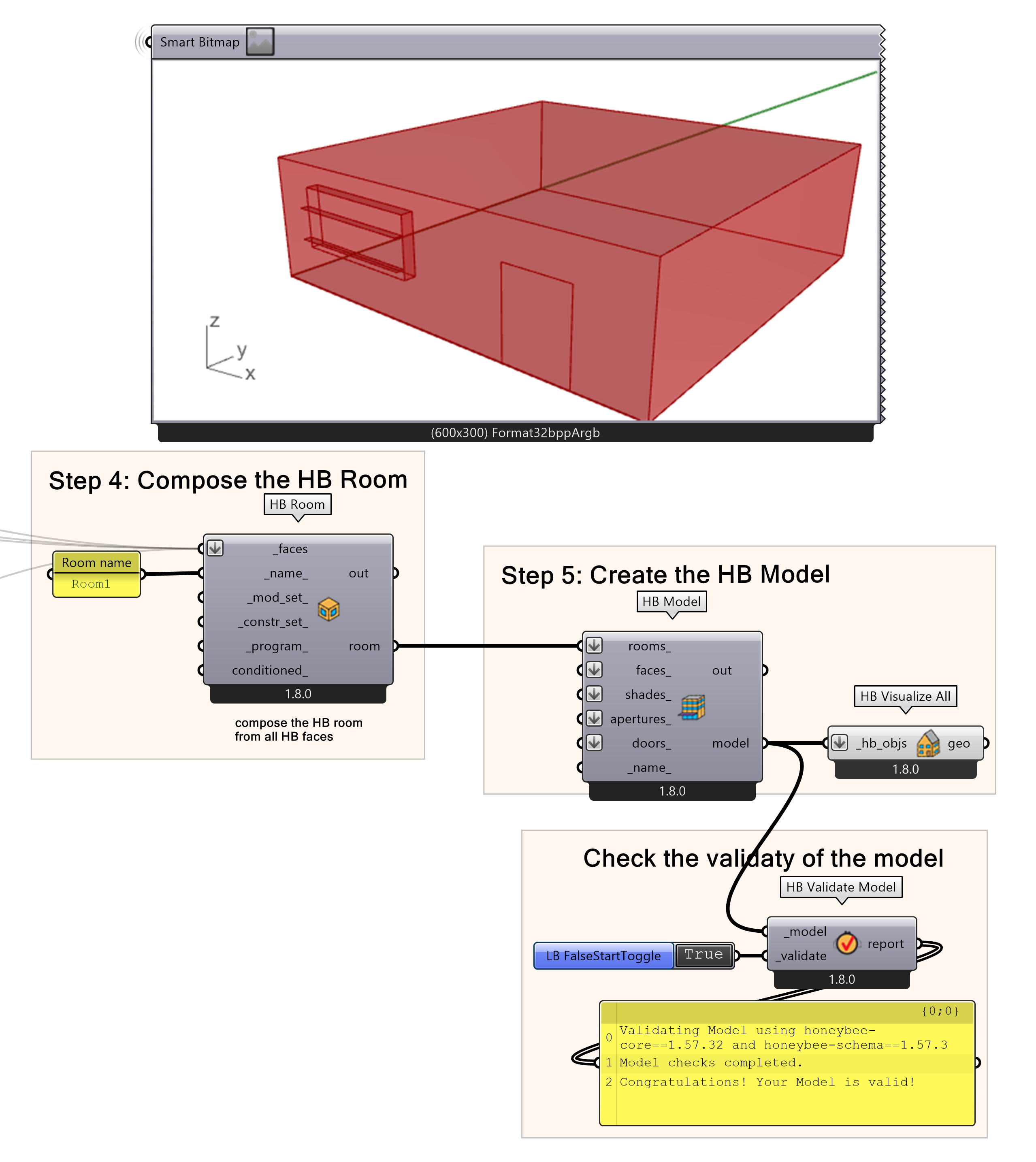
- Create a Room component.
- In the ‘rooms_’ input, add the ‘room’ result from HB Room component
- Create a Validation check component.
- Add a Boolean toggle and run the validation by double clicking.
- Examine the report in a panel.
Honeybee Room set-up 8/10
Visualize & check the HB modellink copied
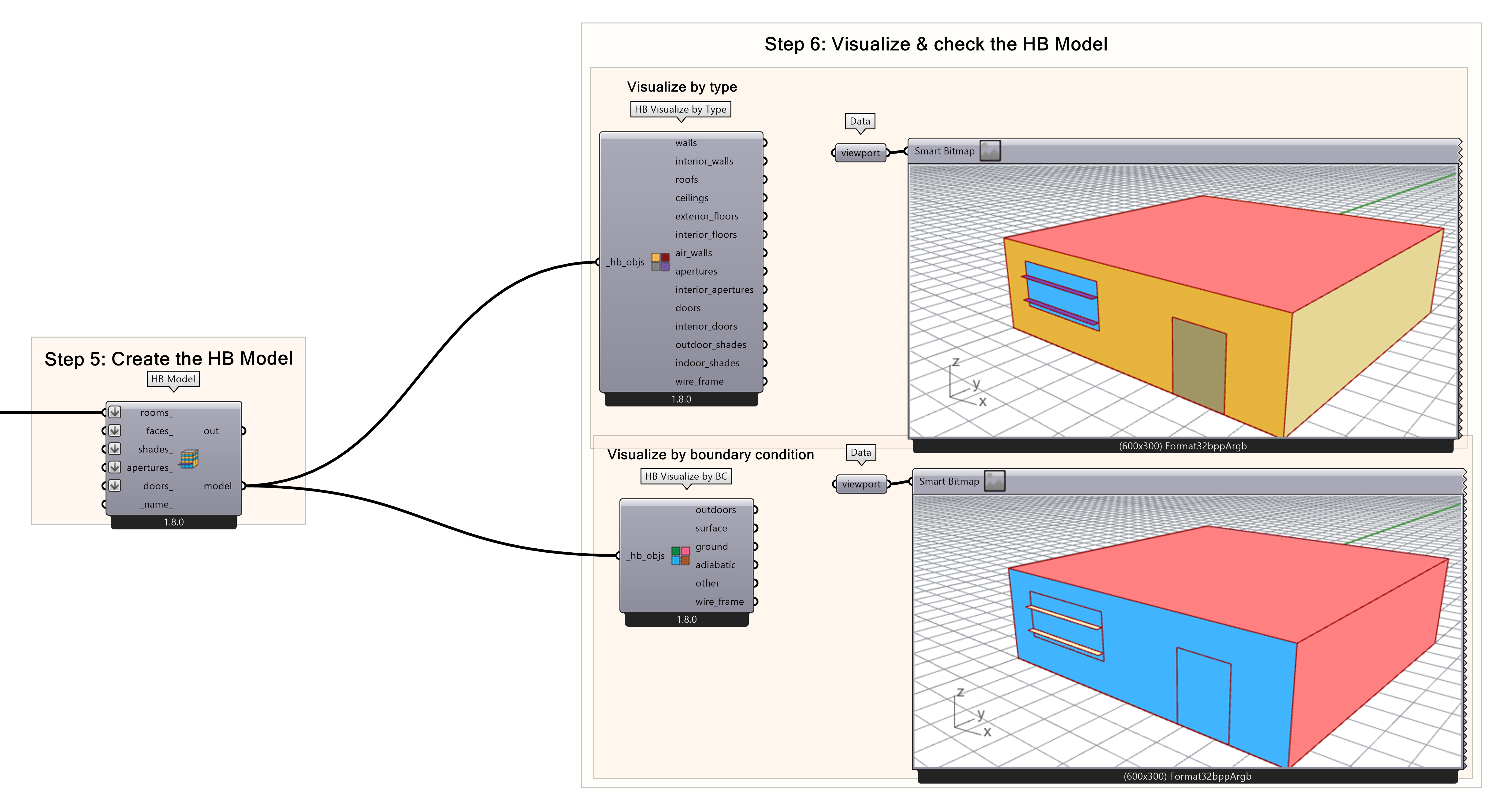
Final step of this tutorial is to visualize the HB model we created. Visualizing the HB model allows you to quickly check for errors during the assignment of the face type or the boundary condition. There are 2 different types of visualization that refer to these categories respectively: visualize by type and visualize by boundary condition. Once you checked the model the preparation is done and the HB model is now ready to be plugged in the analysis simulation. The visualization by type will separate the faces of your model per face type and colour code them. In this way you can check if you connected each surface to the correct HB face type.
- Create a Honeybee Visualize by type component and connect the ‘model’ result from the HB model component to the ‘hb_objs’ input.
- Check each surface for type correctness
The visualization by boundary condition will separate the faces of your model per face type and colour code them. In this way you can check if you connected each surface to the correct boundary condition information.
- Create a Honeybee Visualize by BC component and connect the ‘model’ result from the HB model component to the ‘hb_objs’ input.
- Check each surface for type correctness
Honeybee Room set-up 9/10
Conclusionlink copied
You have now learned how to set up an HB room model that can be used for a daylight analysis simulation. This tutorial provided you with the knowledge on how to set up your geometry correctly from Rhino into Grasshopper by preparing and dividing it into separate faces according to type, setting the HB faces accordingly which are then used to compose the HB room and finally, composing the HB model and visualising the model in two ways to check it. Following this tutorial, you are ready to create and perform a daylight analysis simulation.

Final script
Below you can download the final Grasshopper script. You can use it for other Honeybee tutorials or connect you own geometry with it and create your own HB Model for simulations.
Honeybee Room set-up 10/10
Useful Linkslink copied
If you want to create a more dynamic room, you can check out the tutorial for a parametric room set-up using HB solid room. The tutorial gives the option to create windows by ratio or by specific dimensions.
Follow-up tutorials
These next two tutorials use this room set-up to create and perform the analysis simulations for daylight and energy. Check the following tutorials:
Write your feedback.
Write your feedback on "Honeybee Room set-up"".
If you're providing a specific feedback to a part of the chapter, mention which part (text, image, or video) that you have specific feedback for."Thank your for your feedback.
Your feedback has been submitted successfully and is now awaiting review. We appreciate your input and will ensure it aligns with our guidelines before it’s published.
