Grasshopper Introduction
-
Intro
-
Basics
-
Grasshopper Interface
-
The pull-down menus
-
The Canvas
-
Modules
-
Conclusion
Information
| Primary software used | Grasshopper |
| Course | Grasshopper Introduction |
| Primary subject | Parametric Modeling |
| Secondary subject | General |
| Level | Beginner |
| Last updated | November 27, 2024 |
| Keywords |
Responsible
| Teacher | |
| Faculty |
Grasshopper Introduction 0/6
Grasshopper Introduction
Introduction to parametric modeling in Rhino GRasshopper.
Grasshopper was originally developed to compensate for the limited parametric capability of Rhino. Parametric is the capability for generating interdependencies of components and parameters in this case of the design process.
Grasshopper Introduction 1/6
Basicslink copied
Record History
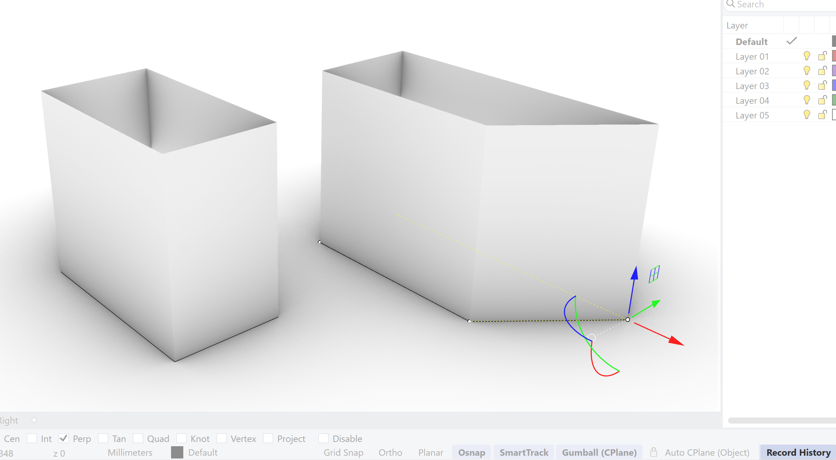
The record history function in Rhino is an example of that interconnectivity. If we generate a curve and extrude the curve we create a surface. With the record history on, the surface created an interdependency with the curve. If I change the curve the surface will follow. With Grasshopper you will build this interdependency resulting in the surface. It is the other way around.

Parametric Setup
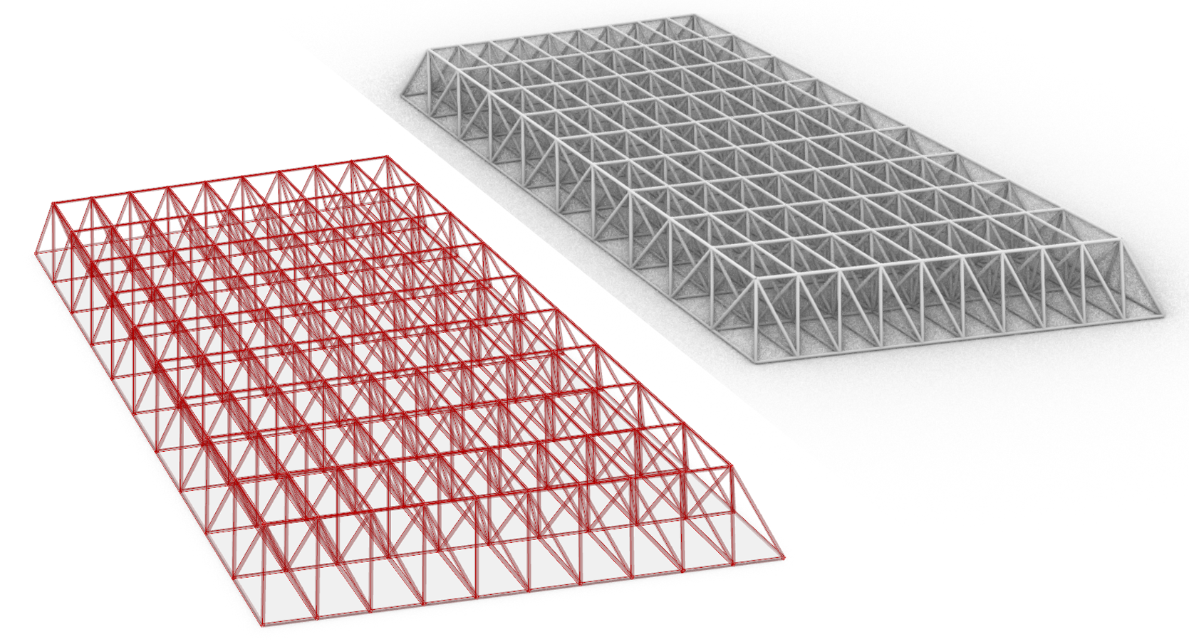
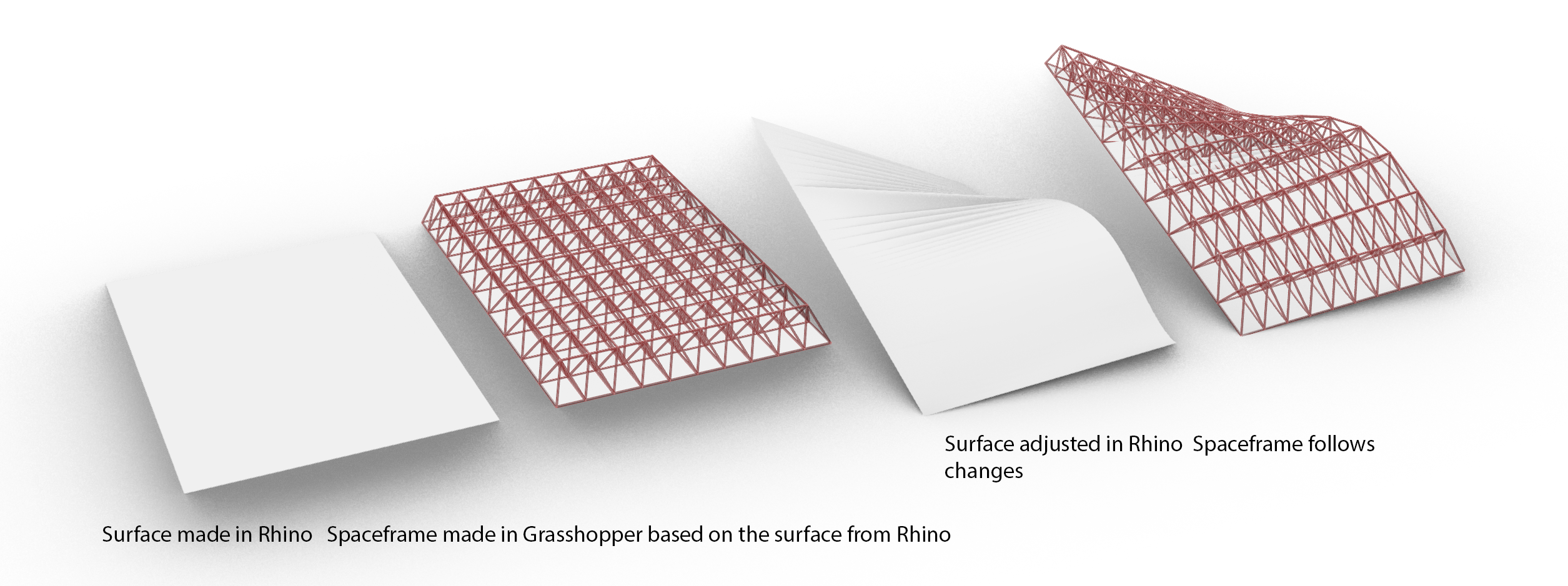
This might sound unimpressive, but above-mentioned functionality is standard in most design software. It allows rapid changes in the design due to its interconnectivity. For example: A roof surface is designed in Rhino. In Grasshopper a spaceframe is made based on the Rhino roof surface. Change the Rhino roof surface and the whole spaceframe will be adjusted.
Grasshopper builds on that principle which allows the creation of a complex network of relationships between a range of objects.
To generate the networks in Grasshopper you use the method of visual programming. This means that Grasshopper uses blocks of code which you can combine into larger networks. This block of code is literally a visual block in Grasshopper with input and output options. The block can contain information, like a curve or surface, number or a letter or it can contain a function like, move, rotate, scale or extrude, sweep 1 rail. You might have noticed that these blocks have a function which is not that different from a command given in Rhino like move, scale and rotate. Grasshopper allows you to use the functionality of Rhino in a visual programming environment.

This results in a very powerful design environment, it is extensively used in architectural design, and enables the designer to generate and develop designs with high complexity of form, functionality or enhanced performance.

Example file
If you are interested what this looks like, you can download the script of the spaceframe. Open the Grasshopper file and look around!
Grasshopper Introduction 2/6
Grasshopper Interfacelink copied
There are two methods to start the Grasshopper plug-in in Rhino.
Starting Grasshopper
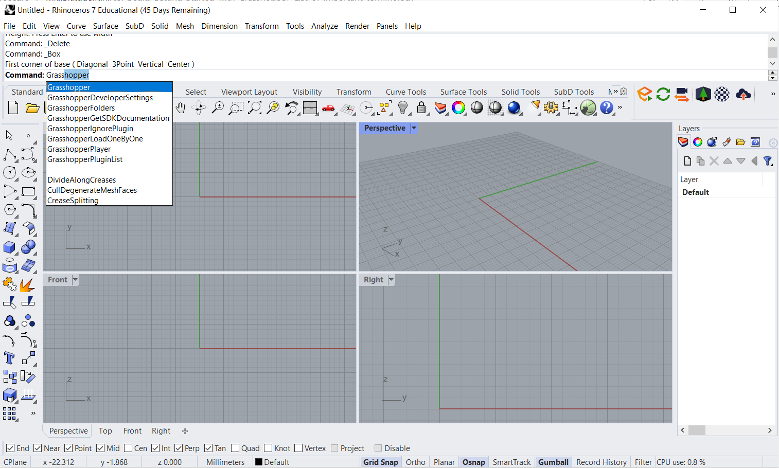
1. You can type ‘Grasshopper’ in the command line.
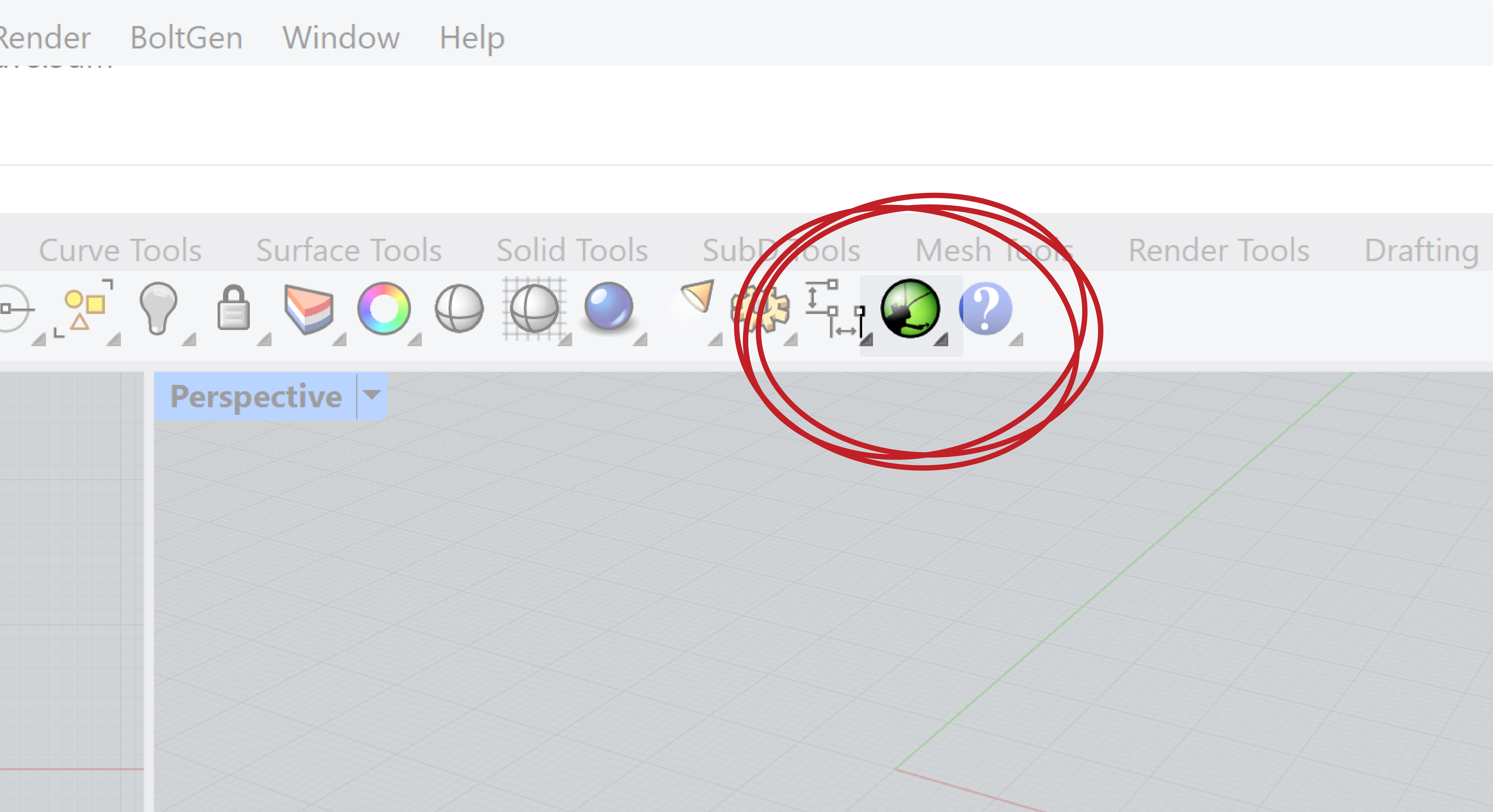
2. Or it can also be opened by clicking on the Grasshopper icon.
Interface
The Grasshopper interface contains:
- A row of pull-down menus
- Tabs with parameters, utilities and components
- Toolbar
- the main workspace or canvas

The canvas is used to create your network – your ‘recipe’. This network is built from parameters, utilities and components. This network in turn will create your model (geometry) in the Rhino viewports. Note that all geometry generated by Grasshopper can’t be selected and modified in Rhino. Geometry created in Rhino, however, can be used by Grasshopper. We’ll get back to this later.

Grasshopper Introduction 3/6
The pull-down menuslink copied
File
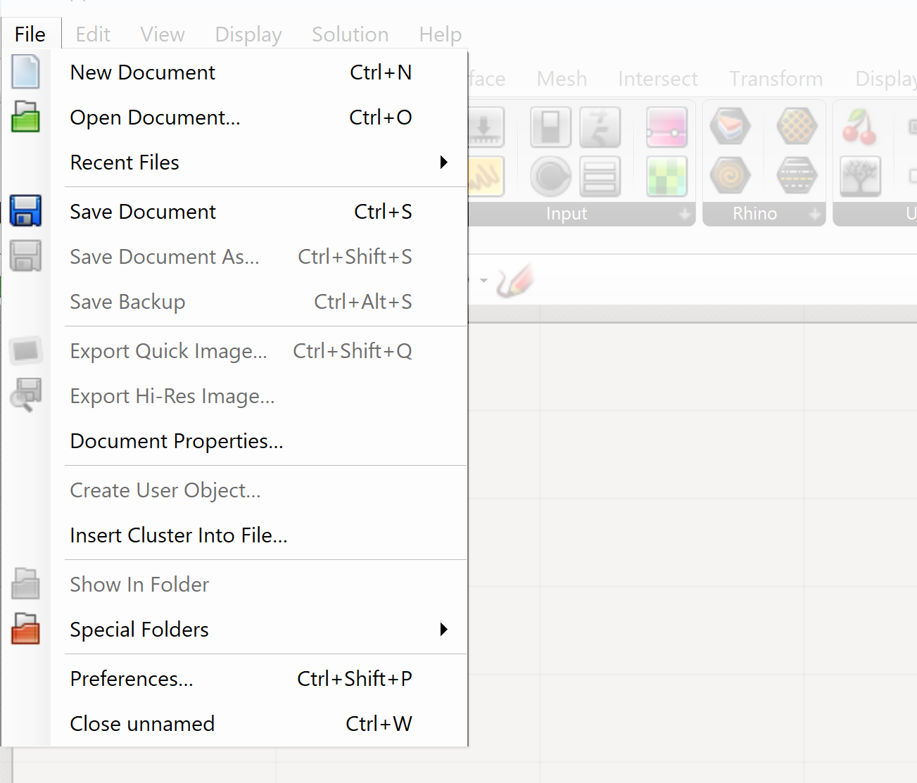
The file menu contains the traditional options for saving and opening files. Note that Rhino and Grasshopper files are always separated. You save your network in the Grasshopper window. If you have used Rhino geometry as a basis for your network, you must save the Rhino model separately in the Rhino window!
Edit
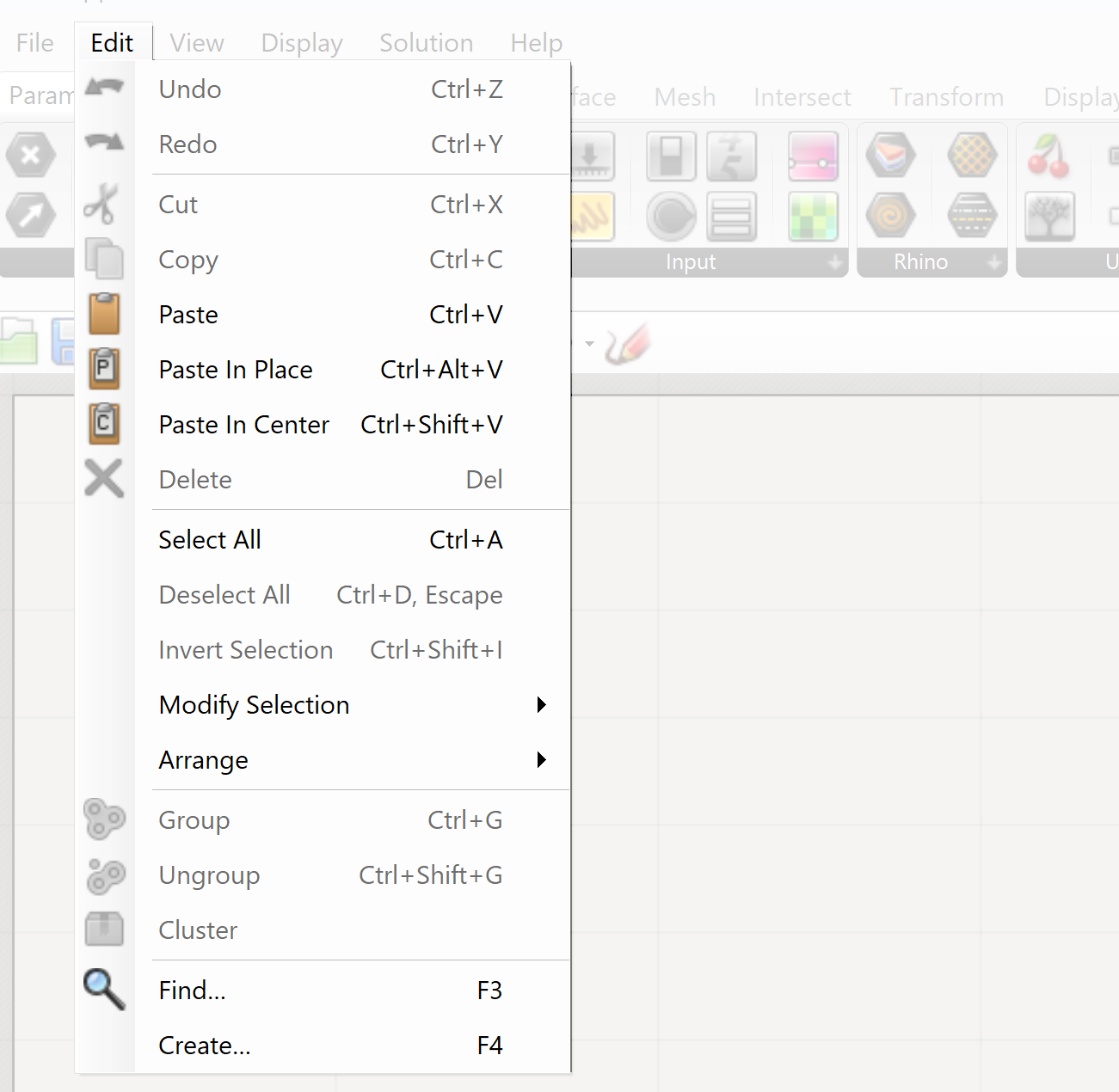
In the Edit option we have the standard copy, paste and selection options as well as the options of grouping. Grouping is essential when the complexity of the network increases
View
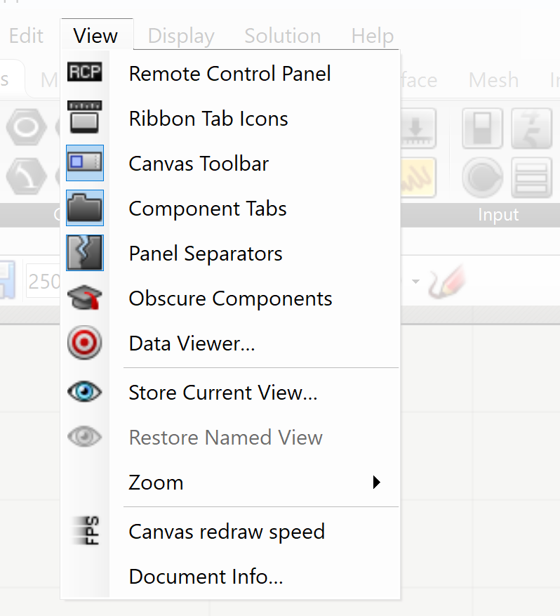
View contains the view options within Grasshopper like zoom. It also contains various options to control how your network is displayed on canvas. We’ll get to these when needed.
At the top we have the Remote-Control Panel. This option will hide the grasshopper canvas and provide you with a smaller menu where all the variables can be accessed. This option is used when you want to avoid the menu of Grasshopper will block your view of the geometry.
Display
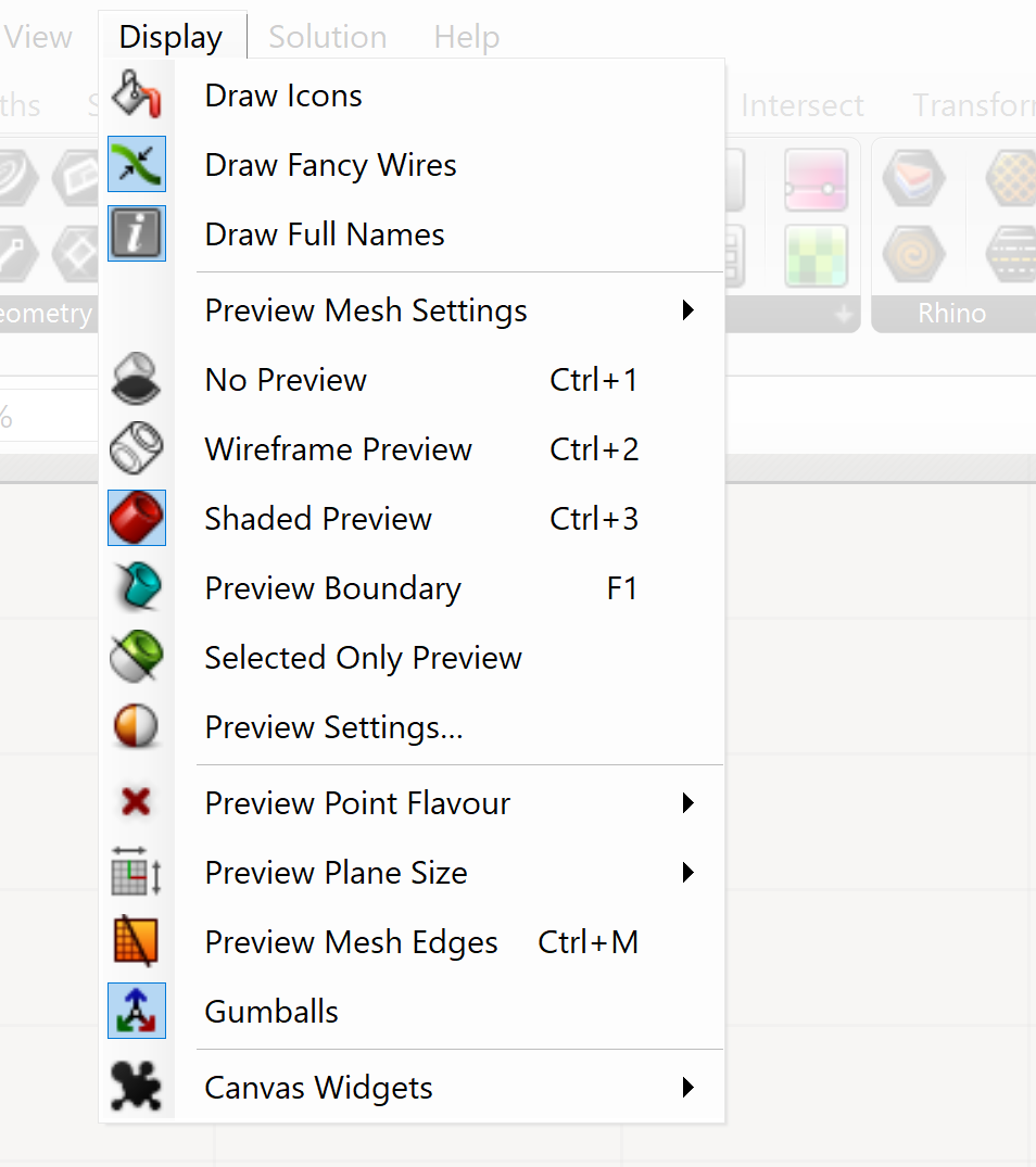
The display menu holds all options to display your script. For example, in the tutorials of the wiki, nodes are always drawn with icons and Full Names of inputs and outputs are visible. You can change all your preferences in this menu.
Specifically useful are the Canvas Widgets on the bottom of the menu. You can use the profiler widget to view the calculation speed of your script.
Solution
The Solution menu contains the settings for the geometry generated by Grasshopper and made visible in Rhino.
- There is a direct link between Grasshopper and Rhino which results in a real-time update of the geometry in Rhino, this is called the preview. This however can be problematic if the complexity of the geometry results into extensive calculations for the update of the geometry. In this case the update can be disabled.
- To finalize the work in Grasshopper geometry must be converted into Rhino geometry. This is called baking. The geometry will be completely editable in Rhino after baking. Although the link with Grasshopper still exists the baked geometry is a copy of the Grasshopper geometry at the moment of baking. Any alterations in Grasshopper will result in alterations of the Grasshopper geometry not of the baked geometry.
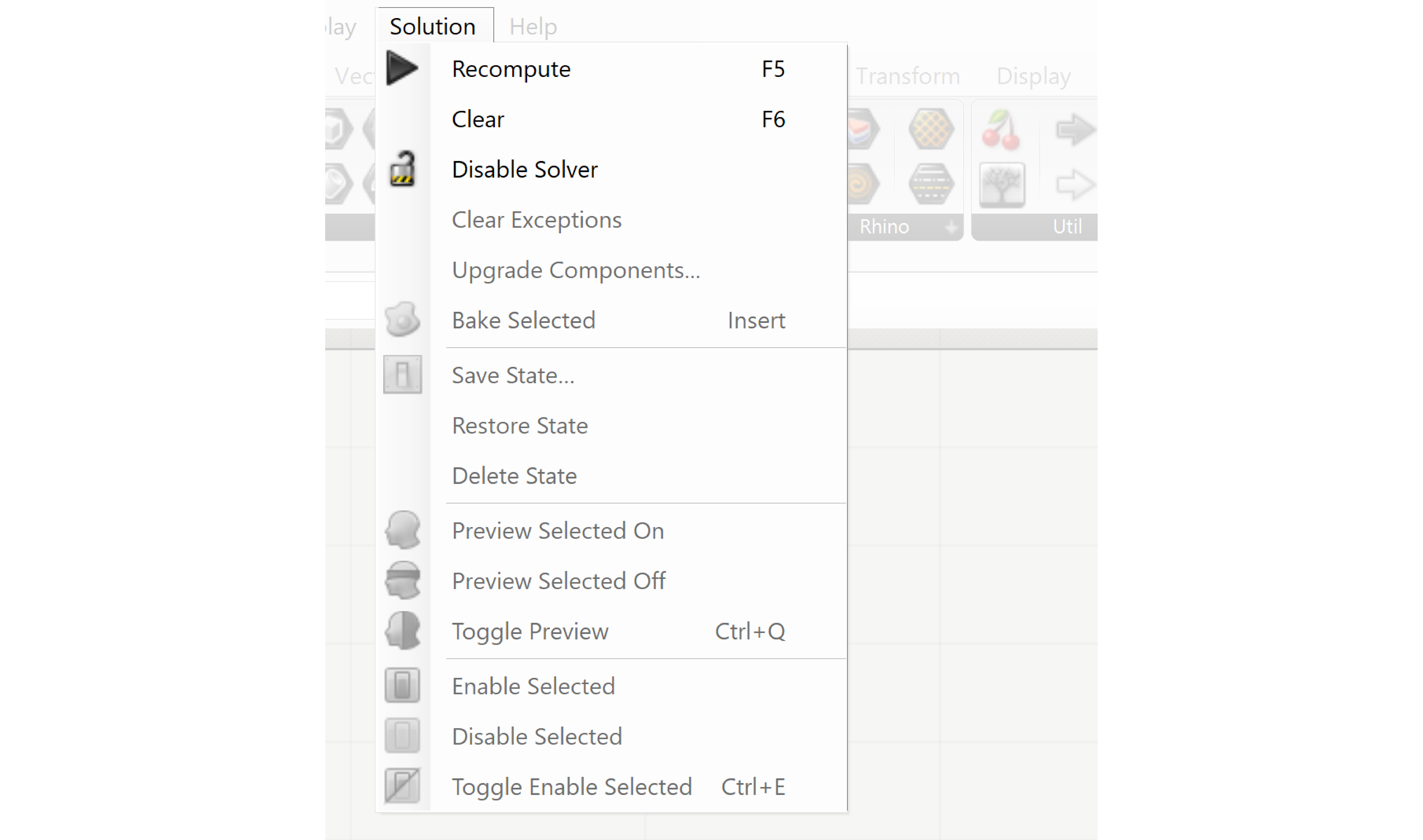
Within the solution menu you can ‘Disable Solver’ or ‘Recompute’.
Tabs
The building blocks that you use to build your network are arranged in various tabs:
- Parameters
- Math – for creating mathematical relations
- Set – List tab where the list can edit
- Vectors, Curves, Surfaces and Meshes
- Intersect
- Transform
- Display
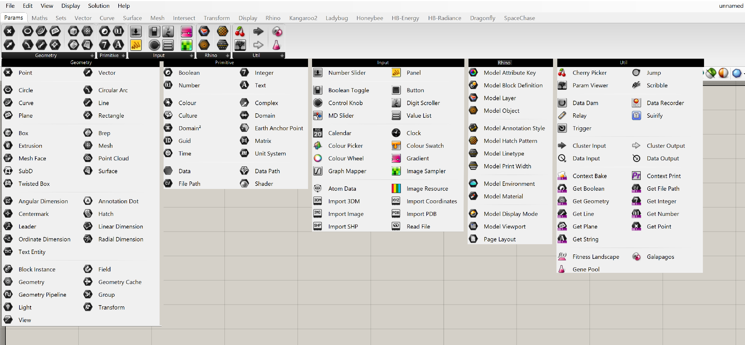
Grasshopper is actively being developed, so this may change from version to version. Each tab is divided into sections to group similar building blocks. Each section shows the most-used blocks. The arrow at the right-hand side of the black section title bar allows you to expand the section to show all available blocks.

Grasshopper Introduction 4/6
The Canvaslink copied
The large window contains the canvas on which the definition is built. Geometry is not visible in this window. The geometry will be represented as a Brep in Rhino. Navigation in Grasshopper is similar to Rhino.

Navigation in the Grasshopper Canvas:
- Pan (move sideways & up/down):
- Zoom:
This page uses abbreviations for the mouse buttons:
LMB: Left Mouse Button
MMB: Middle Mouse Button
RMB: Right Mouse Button
The Canvas Toolbar
The icons bar beneath the Tabs contains the functions for representation of the definition and its related geometry in Rhino.

Canvas Navigation
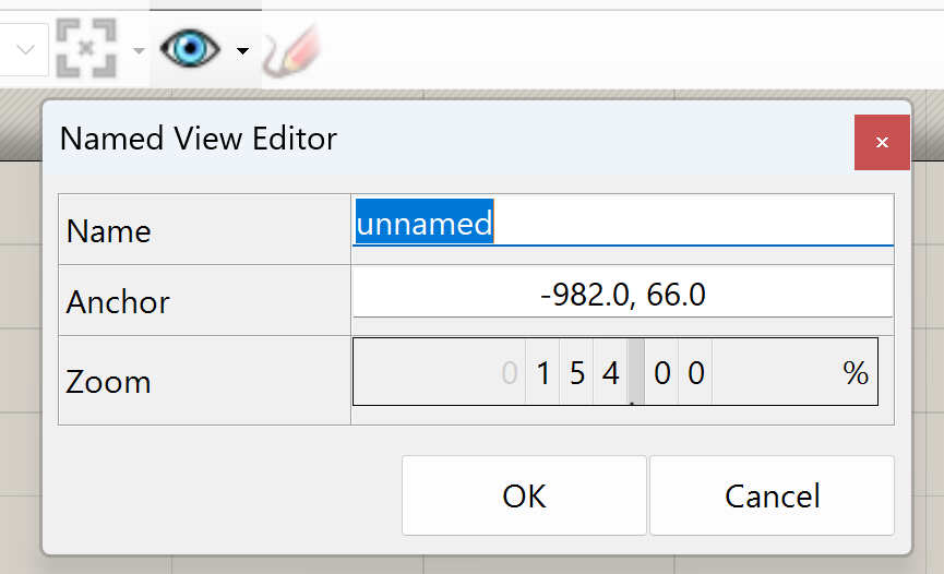
Basic navigation is mostly done by the mouse and keyboard, which was covered in the previous section. Navigating the canvas is also supported by various zoom and pan tools in the toolbar.
The right-most icon allows you to save the current view or restore previously saved views.
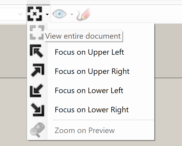
The navigation within Grasshopper is supported by the various zoom and pan tools in the icon bar. Traditional navigation is supported by Right Mouse Button (Pan) and CRTL + Right Mouse Button (zoom). Additional functionality is supported by the icons.
The Pencil
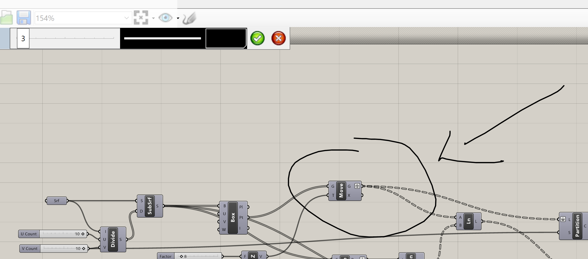
The Pencil icon enables the user to draw in the Canvas. This tool can be used for annotation or, for example, to encircle certain related parameters and components to emphasize their relation. If the curve is right clicked an option menu will appear with edit functions for the curve. The hand drawn curve can be replaced by a curve made in Rhino by using the Load from Rhino option.
Preview
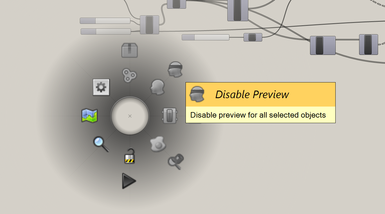
When something is made in Grasshopper a preview of the geometry is created as a Brep in Rhino. The preview can be disabled, or a selection of components can be disabled to save for example calculation time or cleanup the Brep in Rhino. By selecting some nodes and clicking on the middle mouse wheel, you can access options to preview, enable, group and cluster your nodes. This is also possible by selecting the nodes and then RMB on the selection.
Grouping
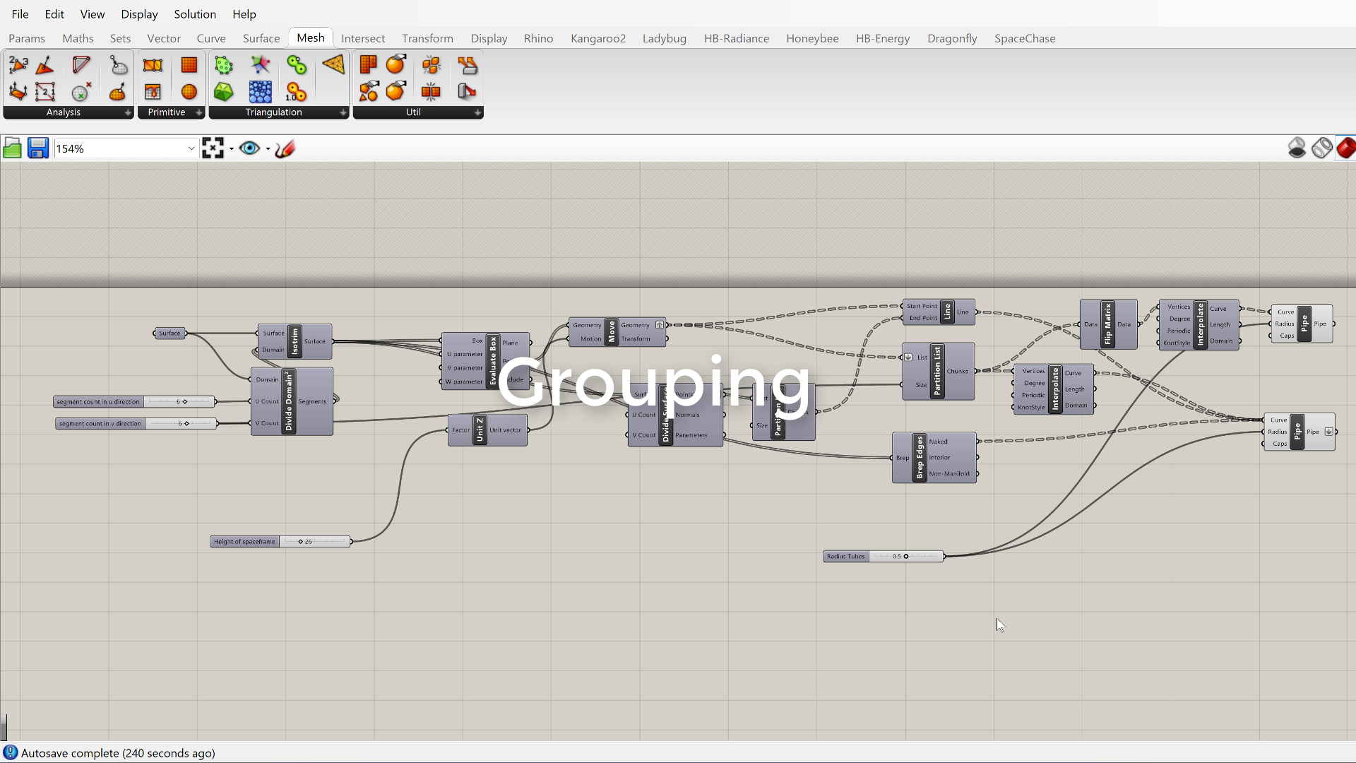
The group is often a set of parameters / components / specials which generate a well-defined function within the network. The group can also be defined by selecting the parameters, components and/or specials and press CRTL+G on your keyboard. Right clicking with your mouse in the box of the group gives you access to the appearance settings of the box.

Solution Representation
The Brep in Rhino is a preview of the geometry made within Grasshopper. To icons on the right give access to the relational settings of the Brep with Grasshopper. To convert the Brep into Rhino geometry the geometry must be baked with the help of the bake icon.
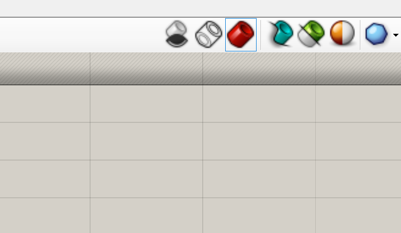
In the solution bar, you will see some options for mesh representation. Meshes can be calculated using the graphics card of your laptop and will therefore be visible way faster than normal Breps. By changing the mesh preview, you can change the quality and speed of your viewport.
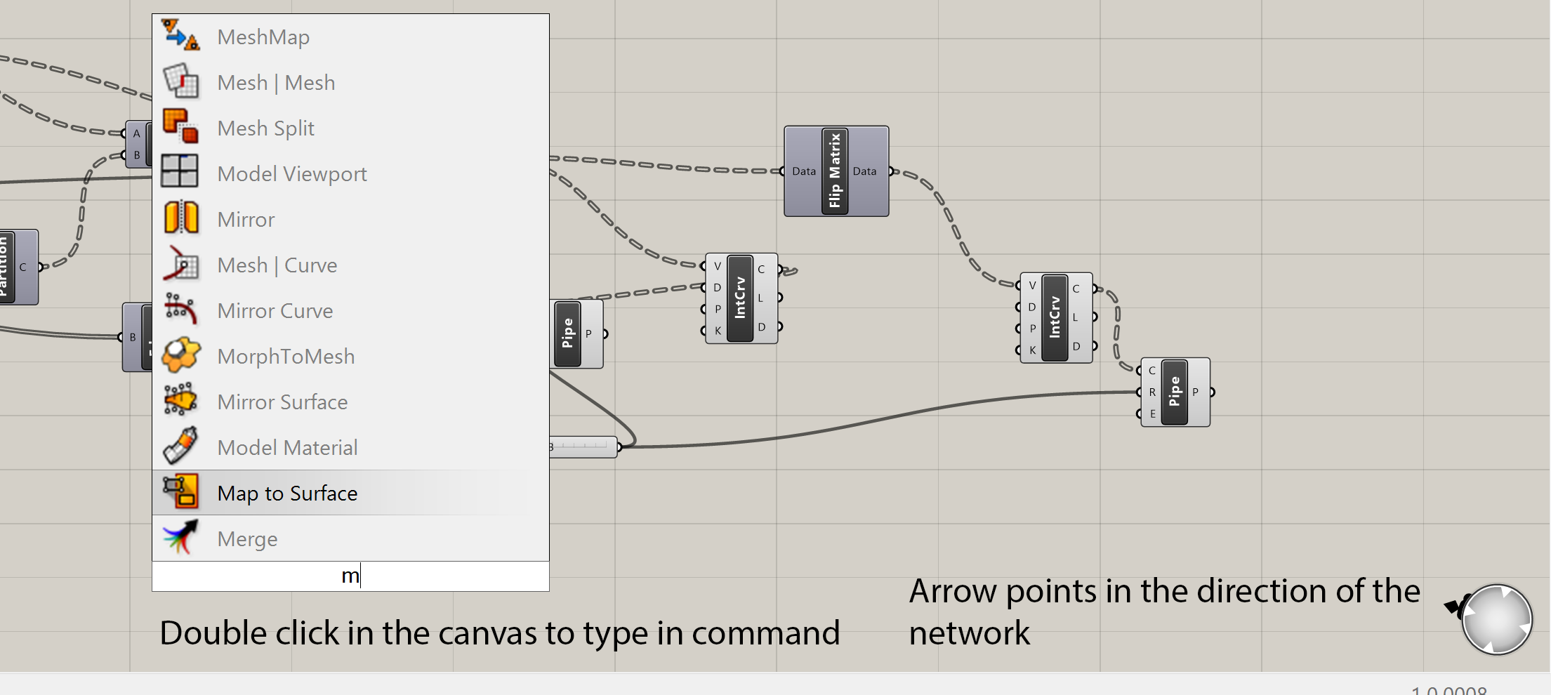
Although you can add nodes by clicking on them in the component tabs, you can also double click LMB on the canvas and enter the name of the object.
Baking
As mentioned earlier, geometry from Grasshopper is not selectable or editable in Rhino. To be able to do this, you will have to ‘bake’ your geometry. Usually, a script developer works according to the following procedure:
- Generate input data for the script in Rhino
- Develop a script in Grasshopper
- Finding the right settings for the model using the available parameters
Baking the geometry back into Rhino.


Grasshopper Introduction 5/6
Moduleslink copied
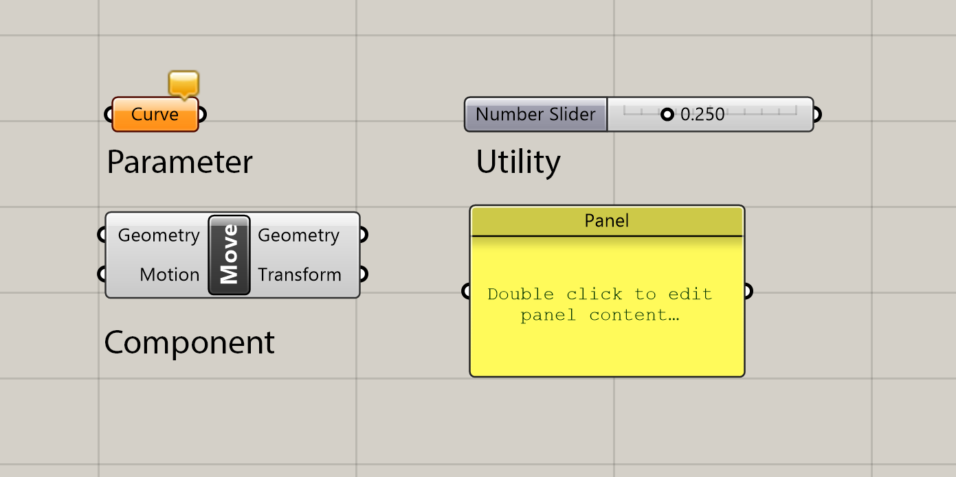
Grasshopper uses a variety of modules which can be interconnected to generate Explicit History. There are 3 types of modules.
- The parameter
- The component
- The utility or special
When you design in Grasshopper you will use these modules to generate the geometry. There are a wide range of modules available which can be combined in various ways with each other. Within all the possible modules you can use are modules which allow you to define values for a range of inputs for modules. This will give you the possibility to steer the result of the definition (your network of modules) which is geometry.

As mentioned earlier in the introduction you construct the generation of geometry step by step. That means that when you start using Grasshopper you will often first analyze how to build the required geometry. What steps do you have to take? Keep in mind many functions in Rhino like drawing a curve are supported by manual input of the mouse. Or settings of that curve can be changed in the command line. In Grasshopper you don’t have that option. You will have to define every step of the process of generating geometry with the help of the modules. Drawing a line is not selecting the curve function and then clicking with the mouse to define the curve, instead it is a process of defining the points of the curve and then generating a curve from those points. This will take some additional effort; however, it allows you to define the points in such a way that you can easily alter them afterwards, in this case with the help of a set of number sliders.
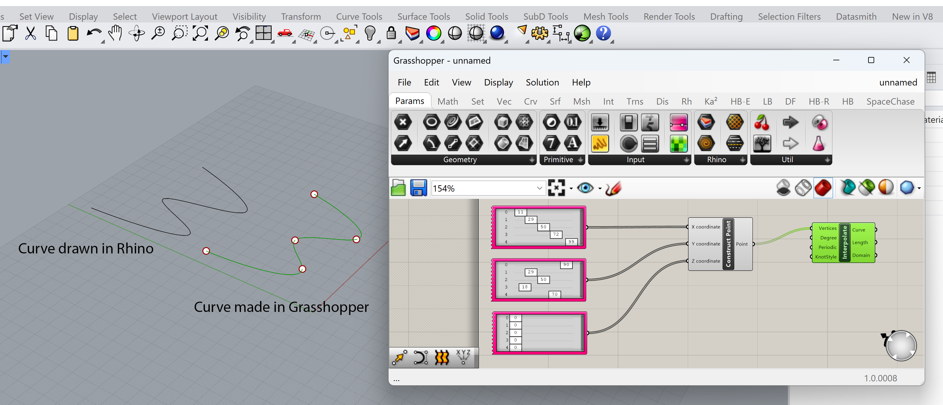
To connect a component to another component, LMB-click the output and drag to the input of another component. To disconnect use the CRTL + LMB and drag the connection in the opposite direction. Alternatively, you can RMB-click an input and use the context-menu to disconnect.
The result is a network of relations and parameters defining the design geometry. The network can be edited and extended during the design process. The design geometry will change accordingly.

Parameters
The organization of the tabs follows the logic of constructing geometry within Grasshopper. The first Tab is the Parameter Tab. The Parameter tab enables you to define geometry and primitives. The specials contain parameters like the number slider and the panel. These specials are defined to support the workflow. The Parameter divers from the components of the other tabs because a parameter primarily contains data. A parameter doesn’t modify the stored data, it will only define the stored data in the network. It works like a filling cabinet.
Parameters primarily contain data; they don’t perform actions. This data can either be used to serve as input for other components or it can be displayed (Panel, Graph). Data can be existing geometry (from Rhino), numbers, text or colors. Geometry parameters are used when you want to use existing Rhino geometry in your definition.


Defining the parameter
When a parameter is placed on the canvas the color is orange, the parameter is empty. The parameter can be dragged onto the canvas or selected in the tab and clicked in the canvas. When the parameter is placed on the canvas it doesn’t contain any information. To define the parameter geometry or a primitive has to be defined. It is possible to define one or multiple similar types of geometry or primitives within the parameter. To define a single or multiple geometrical objects, right-click on the parameter and use the selection option.

There are two options for creating content for the parameter. It can be defined in Rhino or in Grasshopper. This will depend on the mathematical description of the geometry in Grasshopper. If this is similar to Rhino, the geometry can be defined in Rhino. If it is not similar, for example with the definition of a circle, the geometry is made within Grasshopper.
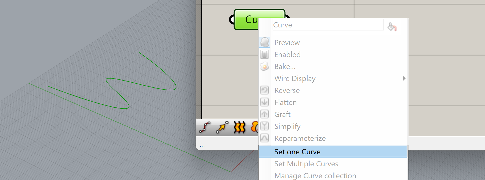
To define the parameter with a geometry from Rhino, click on the “Select one” or “multiple objects” depending on the amount of objects you want to define in the parameter.
The geometry of the Parameters can be defined in Grasshopper or Rhino. A circle for example has to be defined within Grasshopper because the definition of a circle in Rhino differs from the parametric definition of the Grasshopper circle. This difference in definition will depend on what Parameter is defined. A point for example can be defined in Rhino as well in Grasshopper. This difference in definition will dictate the possibility of changing the geometry later in Rhino and not only in Grasshopper. Although this seems trivial, it will greatly influence the design process and the capacity to effectively alter your design geometry. If the content of the parameters is defined in Grasshopper, the options of modifying the geometry in Rhino itself will be lost. If however, the content of the parameter is based on Rhino geometry the geometry can be altered in Rhino resulting in a modification of the whole Grasshopper geometry.


Components
Each component performs a specific action. Most components require input and provide output.

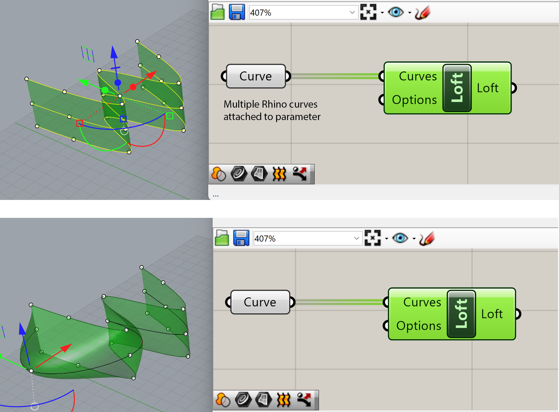
For example: the Loft component creates a surface between two or more curves. So, it has an input to specify which curves should be used for the loft. The output specifies the surface (or surfaces) that is created by the component’s action.
The output of a component can be connected to another component to serve as an input. In our Loft example, the output (a surface) can be the input for the Divide Domain and Iso Trim component, that subdivide any given surface. Or it could be fed into a Move component that creates a moved instance of the input geometry.


This is in essence how designing your Grasshopper definition works. You use components (inputs and actions) and connect them to other components to generate or manipulate geometry. A Grasshopper definition is in essence a cookbook that represents your design idea.

Specials
The specials contain a variety of functions which support the easy access and manipulation of the network. We can in some cases also use a Special for the input or output of a component. The most used are the
- Number slider
- The Panel
The number slider will enable you to define a number within a certain range and type. If you want to be able to move the curve of a loft, you can add a transform component to the curve and manually define the transformation with the help of the slider.

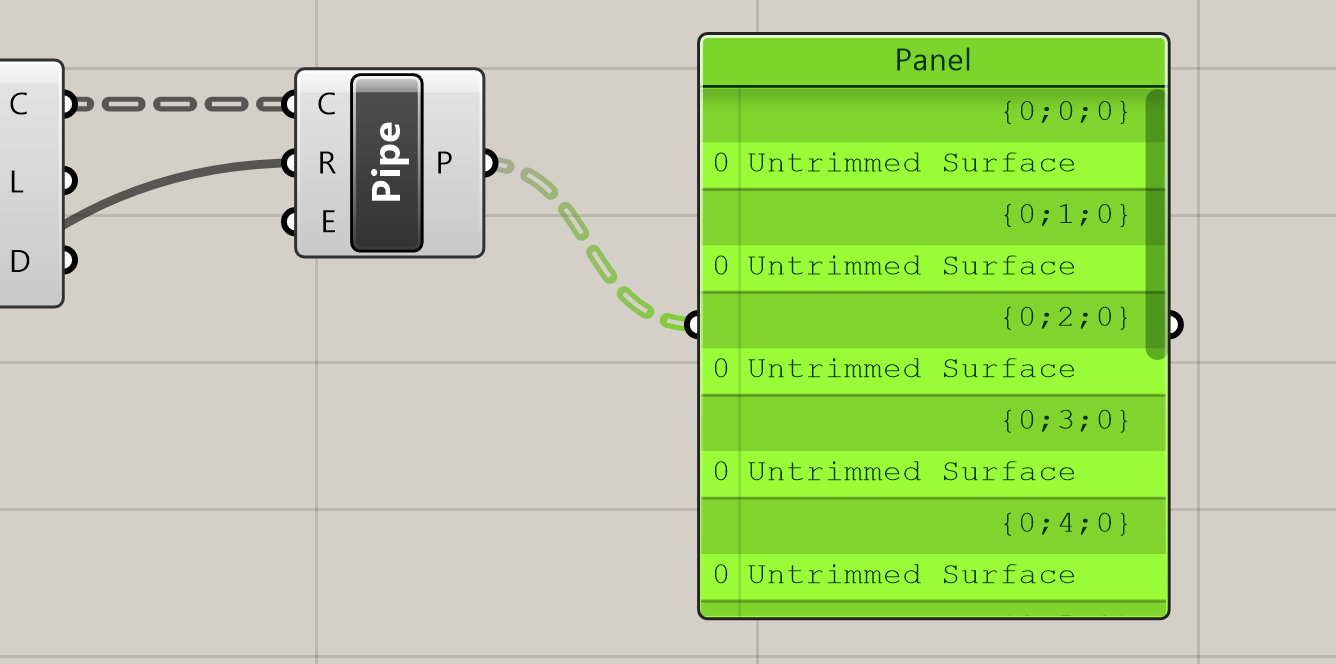
The panel will give you feedback on the output of the components. This can be of use when you want to explore the list you want to edit. Using Panels to display data is very useful to debug your Grasshopper definition. If something doesn’t work properly or behaves differently than you expected, you can connect Panels to the output of components at various locations in your definition to try to understand what is going on.

Grasshopper Introduction 6/6
Conclusionlink copied
You now explored the basics of Grasshopper for Rhino, which will set you up well to learn more about almost endless possibilities of this toolset. You will probably go back to this tutorial couple of times while learning new interesting functionalities, and that’s fine!
Good luck with the upcoming tutorials.
Write your feedback.
Write your feedback on "Grasshopper Introduction"".
If you're providing a specific feedback to a part of the chapter, mention which part (text, image, or video) that you have specific feedback for."Thank your for your feedback.
Your feedback has been submitted successfully and is now awaiting review. We appreciate your input and will ensure it aligns with our guidelines before it’s published.
