Creating surfaces in Grasshopper
-
Intro
-
Extrude curve
-
Loft
-
Sweep 1 Rail
-
Patch
-
Conclusion
Information
| Primary software used | Grasshopper |
| Course | BKB2WV3 – Digitale Ontwerpomgeving |
| Primary subject | Parametric Modeling |
| Secondary subject | General |
| Level | Beginner |
| Last updated | November 27, 2024 |
| Keywords |
Responsible
| Teacher | |
| Faculty |
Creating surfaces in Grasshopper 0/5
Creating surfaces in Grasshopper
In this tutorial you will learn how to generate surfaces in Grasshopper.
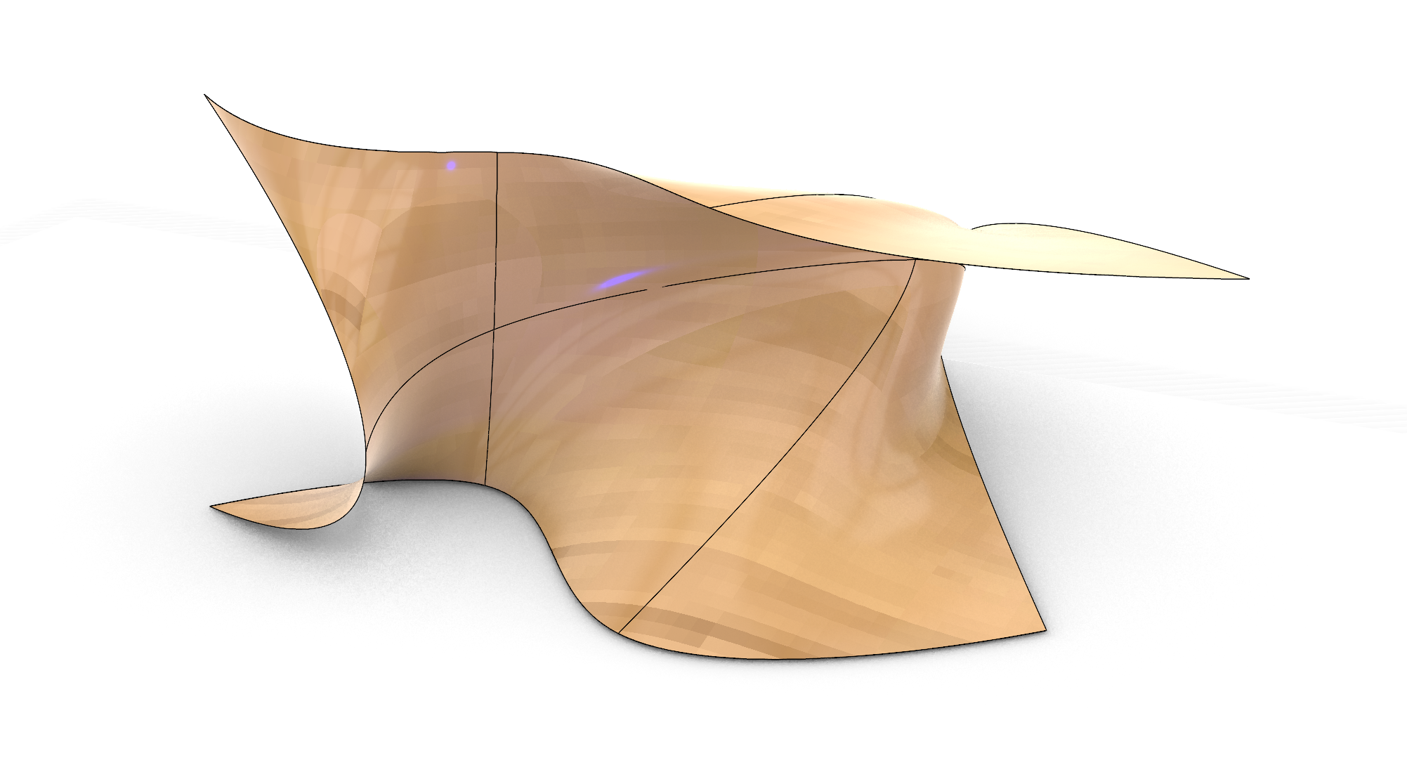
Creating surfaces doesn’t differ much from generating them in Rhino. The main four modeling options of extrude, sweep 1 rail, loft and planar are also available in Grasshopper. However, the major difference is the geometry input. This can be a set of points or curves. Especially the use of points is something which is less used in Rhino. Points in Grasshopper can be useful for coupling it to other parameters, influencing the location of the points. Thereby creating triggers which might deform the surface.
The techniques are relatively the same in Rhino as in Grasshopper. We have the main four options of:
- Extrude
- Loft
- Sweep 1 rail
- Patch
Creating surfaces in Grasshopper 1/5
Extrude curvelink copied
The example uses the extrude component to extrude an existing curve in Rhino.

Add a curve
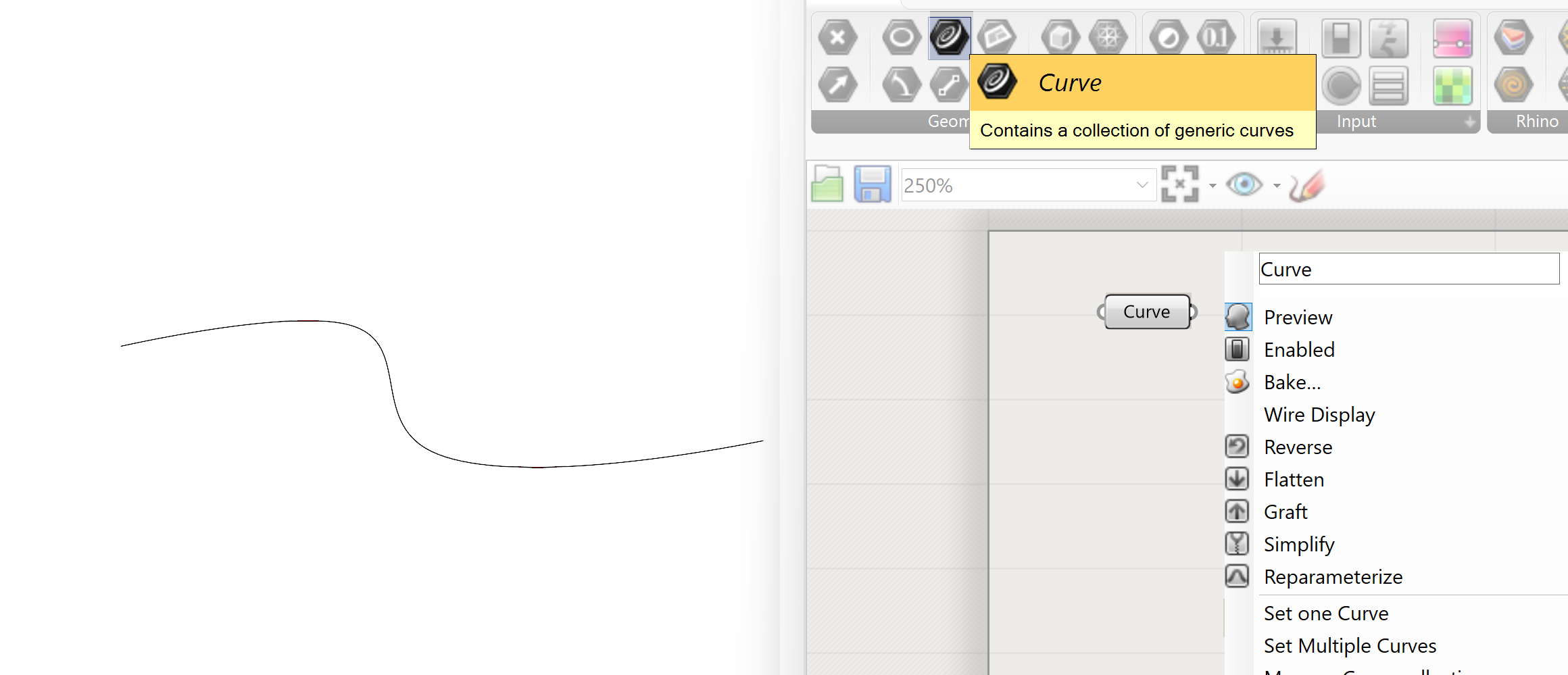
Add a Rhino curve to a Grasshopper Curve parameter
- Set a curve created in Rhino to a curve parameter in Grasshopper
Add a vector
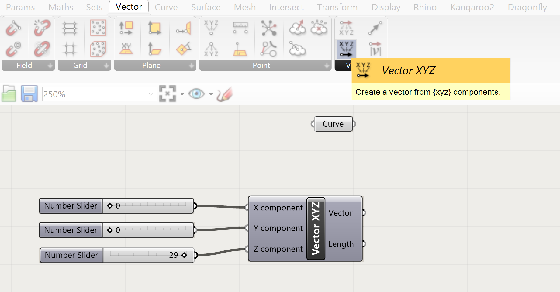
Add a vector, which will determine the direction and distance of extrusion, with number sliders to the canvas. That is one option that allows you to define the direction in the X,Y and Z direction.
Add vector amplitude
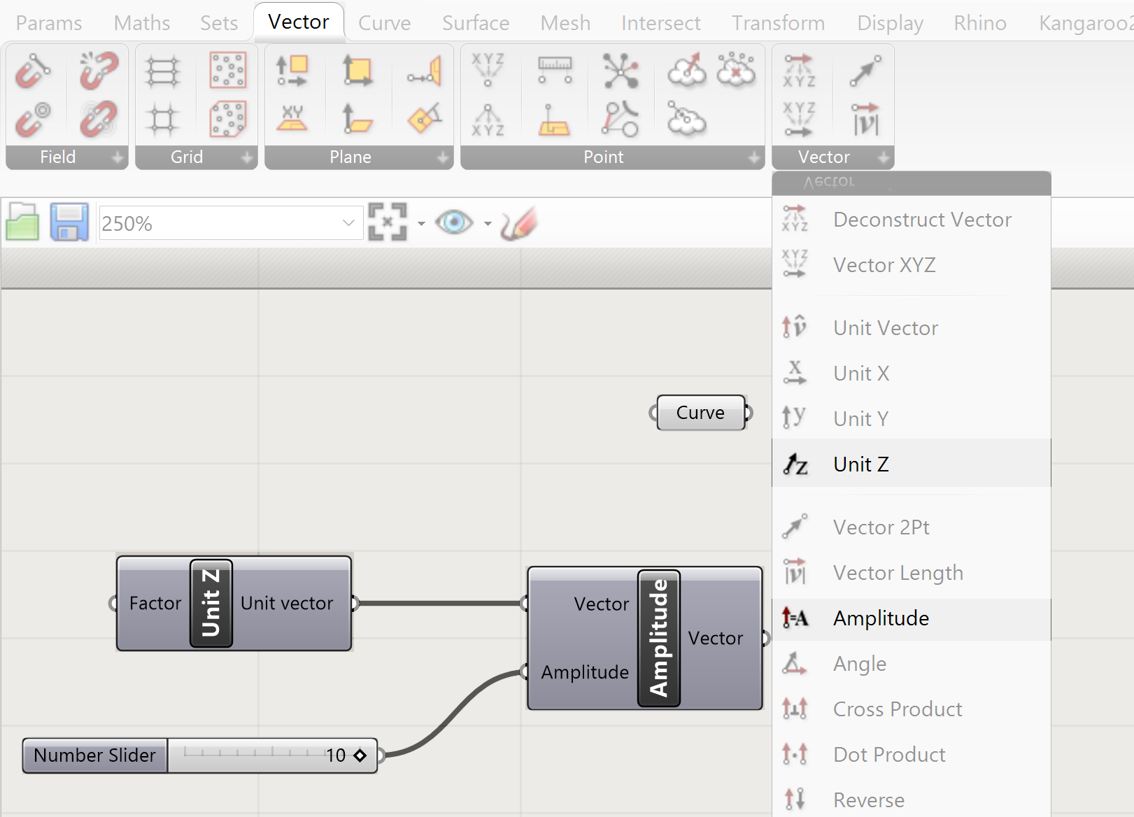
The extrude component is used to make a straight extrusion. Another extrusion option is also available. The direction and distance are controlled by a vector.
Add a vector to the canvas
(this provides a vector in Z direction with the distance of 1)
Add an Amplitude component
Add a Number Slider
The distance of the vector is controlled by the amplitude. This is, in fact, the length of the extrusion.
Extrude
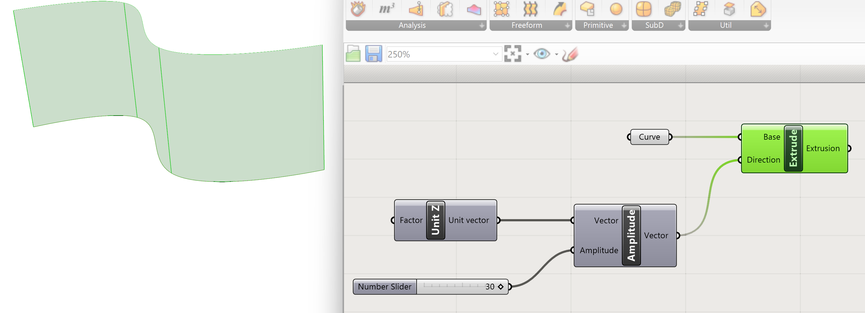
Add an extrude node to the canvas, connect amplitude to direction and curve to Base
- Use Amplitude vector component to extrude the geometry
- Draw a connection line between the amplitude output and direction input
Bake
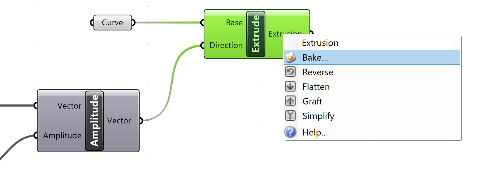
Your script is now finished. You can “bake” the object by right-clicking on the surface parameter and click on bake. This will get your surface into Rhino for further modelling.
- Bake your final surface:
Creating surfaces in Grasshopper 2/5
Loftlink copied
Curves as basis for loft
A loft enables you to make a surface between several curves. This can be 2 or more. There are several ways on how to do this. This example is for creating a loft with a limited amount of curves and the option to transform one or more of the curves. This transformation of one or more of the curves will influence the resulting lofted surface.
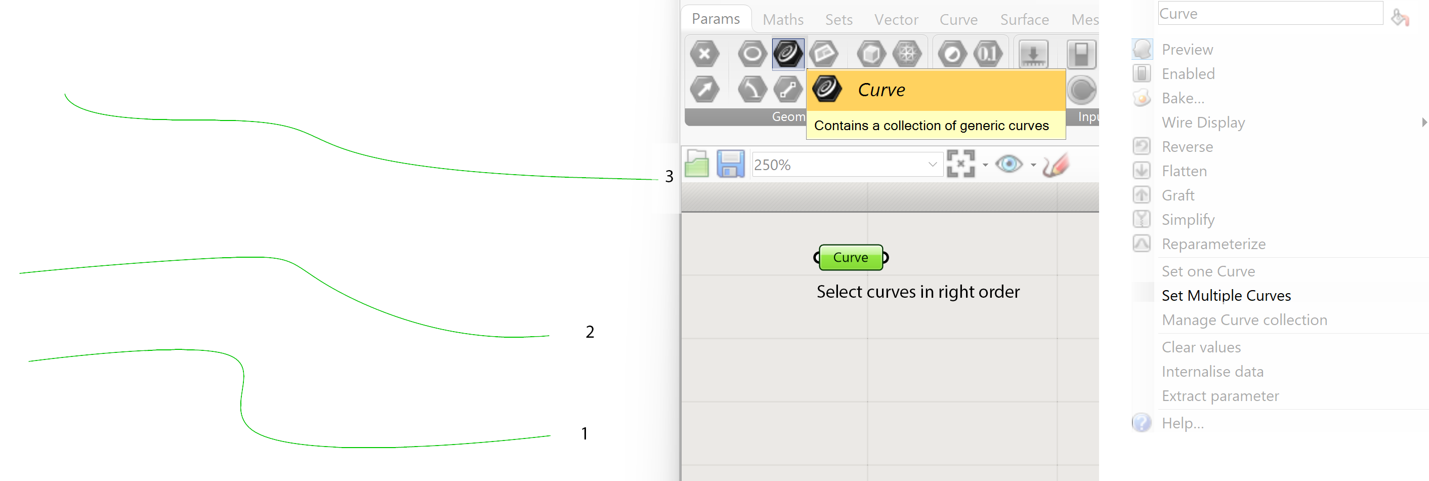
To create the loft, we need at least two curves. In this example we use 3 curves generated in Rhino and then connected in Grasshopper with a Parameter>>Curve. Right click on the Curve parameter and select Select Multiple Curves. Make sure you select them in the right order. The surface will be created according to the order of the curves.
Loft component
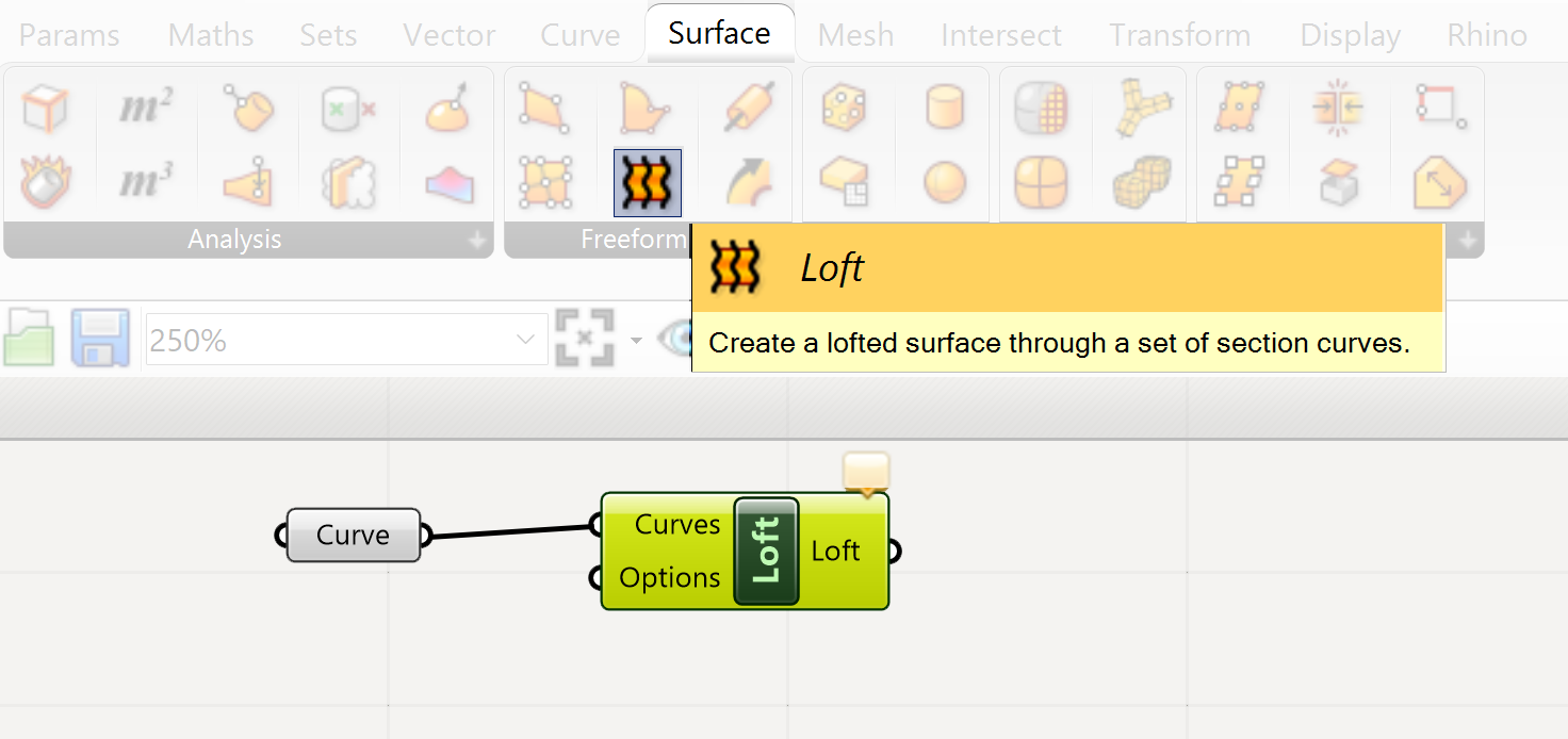
The Loft component can be found under the Surface tab
Connect the Curve parameter with the Curves input of the Loft component. The surface is generated between the curves. If one of the curves is transformed in Rhino or Grasshopper the surface will be adjusted accordingly.
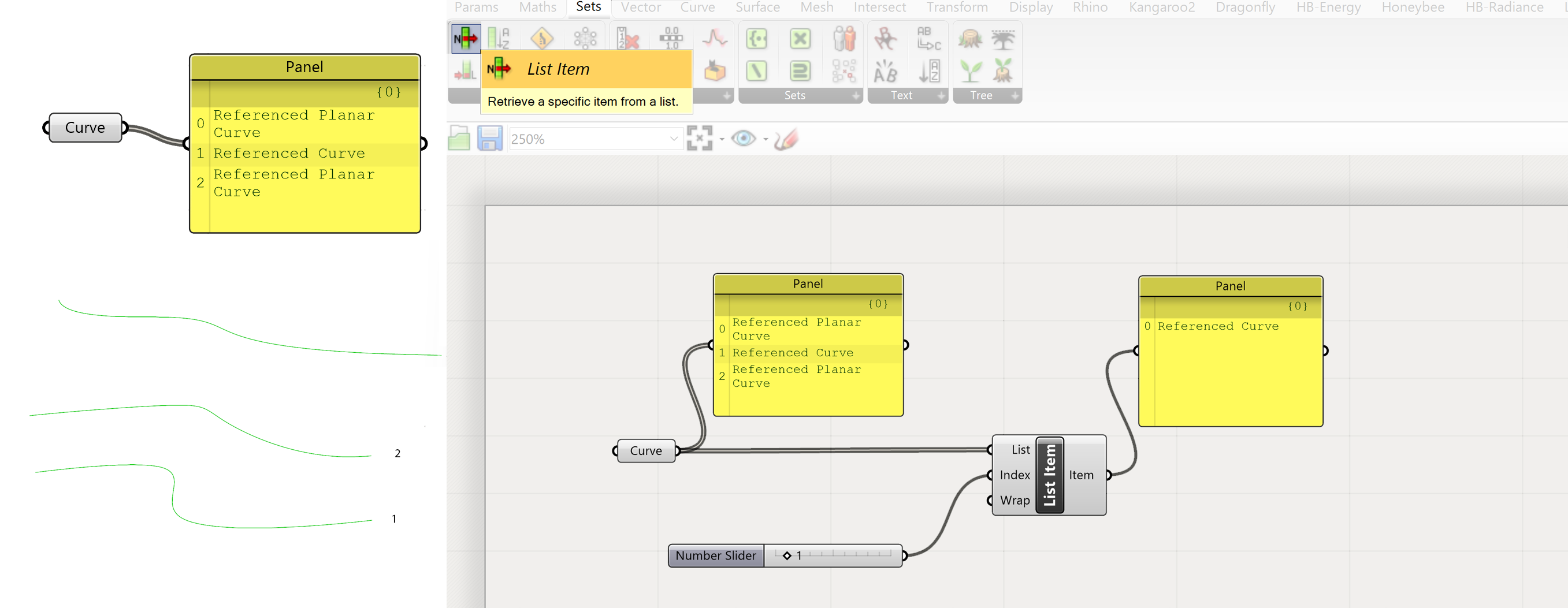
List Item
When you have existing curves that you use to make a loft, you may want to change the position of these curves. You can do this using the move or rotate component. The move component uses vectors to specify the direction and distance.
- We have in the Curve parameter several curves connected. If we want to move 1 we have to select it from the list of curves. This can be done with the:
- Connect the Curves parameter with the List Item component and add a numberslider to the Index input of the List Item component. This will select the curve with index number 1 from the curve list.
- This curve can now be moved
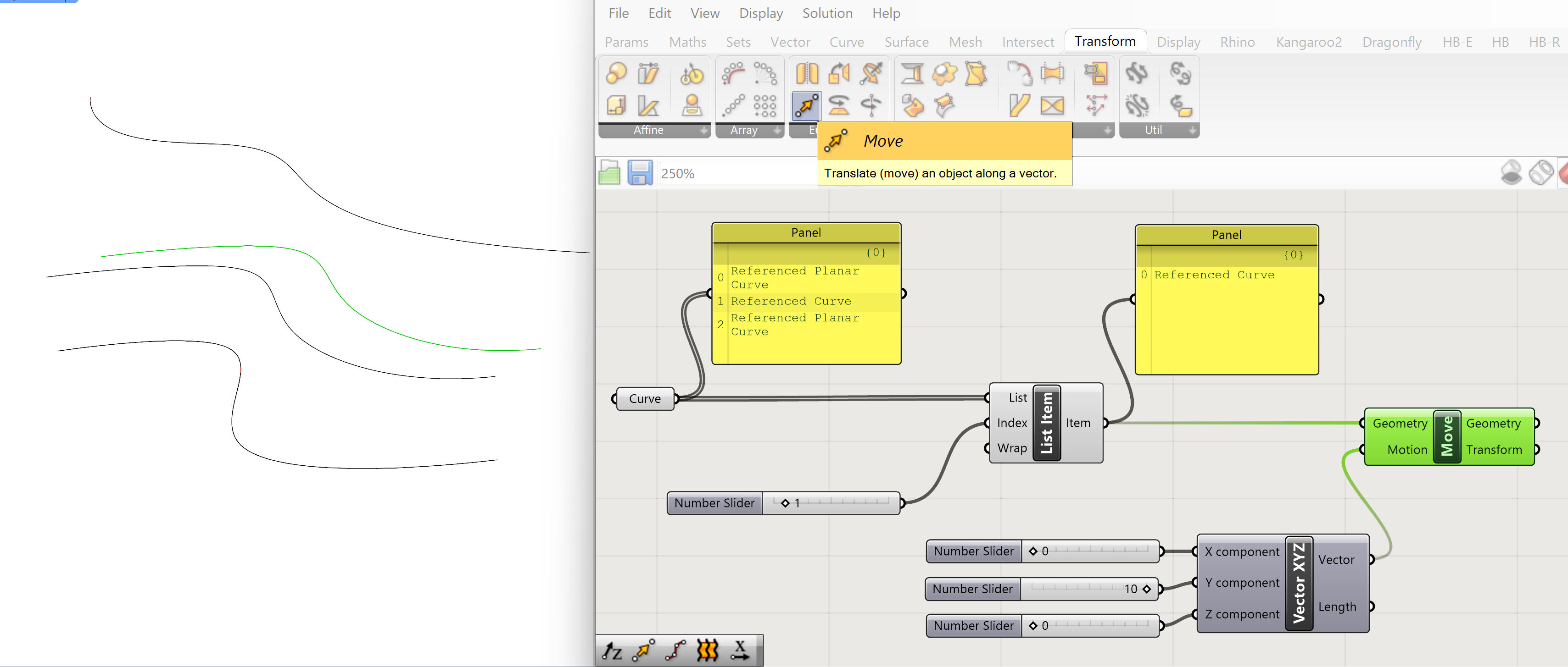
Move
The is moved in the Z-direction and X-direction by using a Construct Vector component. The length of the movement will be dictated by the numerical input of the x, y and z value. input with a Number Slider.
- Add a move component to the script
- Connect a Construct Vector component to the motion input
- Add a number slider to the x,y and z of the Construct Vector input by
- These sliders will determine the amount of movement.
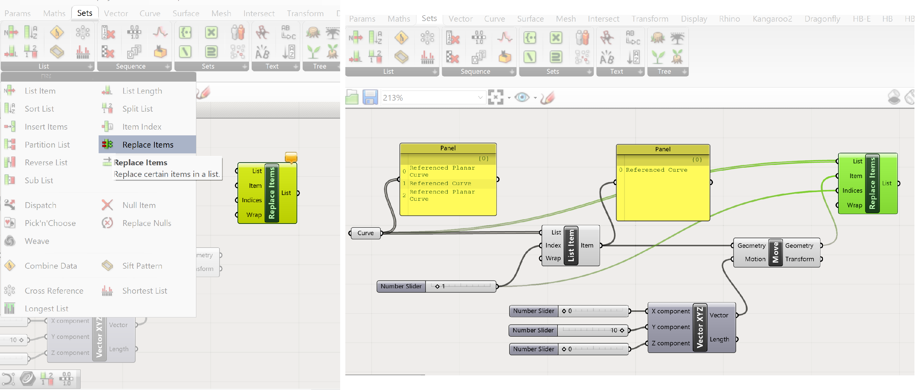
Replace Item
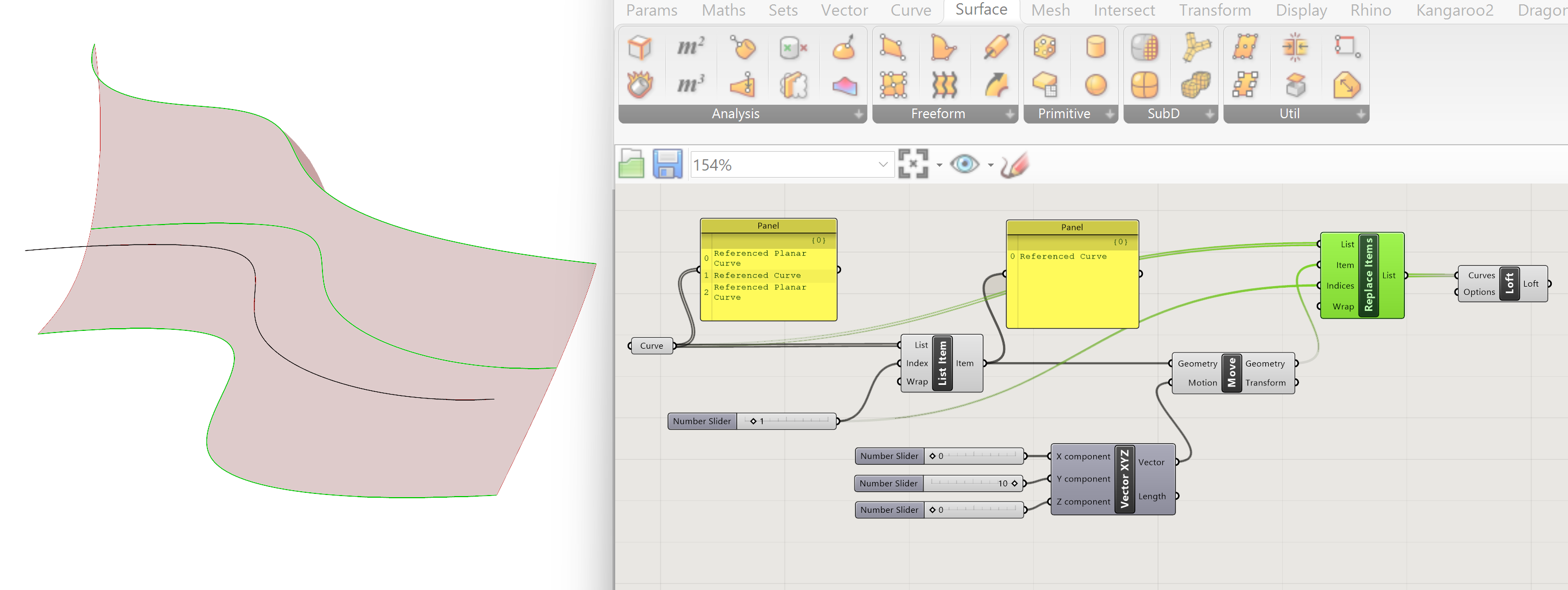
Because we changed one of the curves the Loft has to be remade with the new moved curve. ( it doesn’t automatically update the old loft, changes made don’t work backwards in the network )
We have to construct a new list with the two old curves and the new adjusted one. We have to replace curve with index number 1 of the old list with the new moved curve.
- Move the transformed curve into the curve list of the loft , replacing the original , not moved curve. Use the “Replace” component:
- Connect the Curve output to the List input of the Replace Items component. This will read the old list of the curves.
- Connect the Geometry output of the Move component with the Item input of the Replace Items component. This will define the new moved curve.
- Connect the Numberslider, which is used for the List Item component, to the Indices input of the Replace Items component. This tells which curve in the old list has to be replaced.
Adjusting loft
We now have a new list with two old curves and 1 moved curve. This new list can be used for generating a loft. If the moved curve is adjusted by changing the x, y and z values of the Construct Vector component, the loft will change accordingly. This is a simple example of a parametric model.
Rotating curve
Of course, you can also rotate the moved script. This will result in the following script.
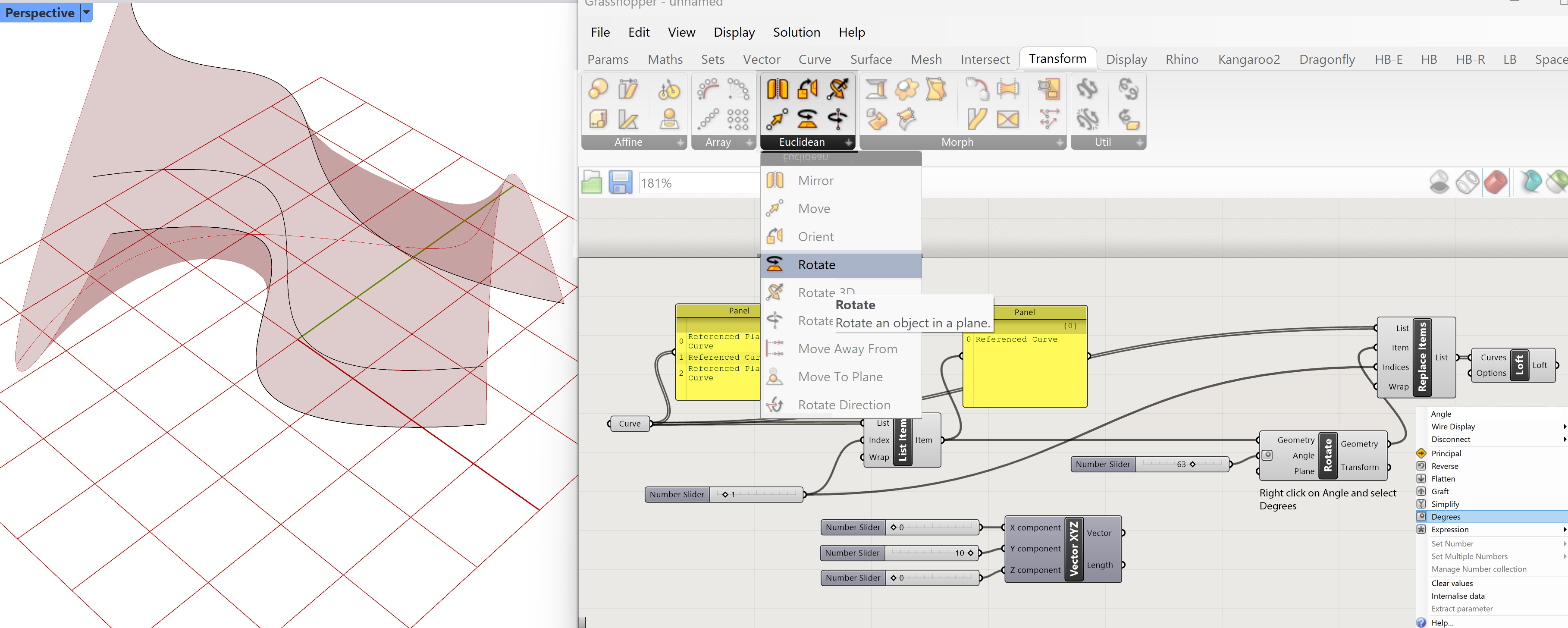
In setup is the same as the move script. We extract one curve from the original curve list and change that curve. Next we integrate the adjust curve in the original curve list and create the loft.
Go for rotate:
The output of the List Item component is connected to the Geometry input of the Rotate component. (this is the selected curve to be rotated)
Right click on the Angle input of the Rotate component and select the degree option. This means that the input is interpreted as degrees.
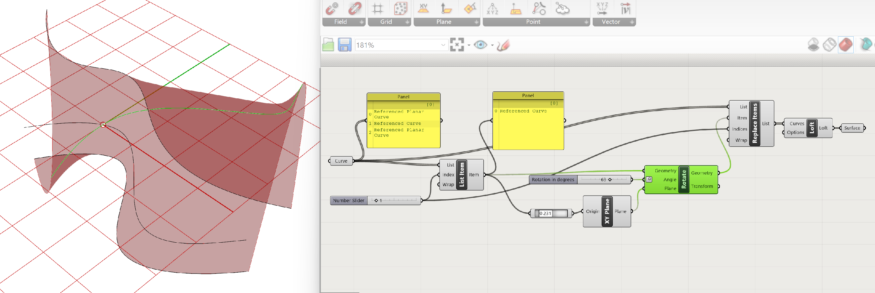
In this case we use a default plane for the Plane input of the Rotate component. This means the curve will be rotated in the X-Y plane with the origin of the grid as location for the rotation axis. This is not ideal.
Point on Curve
To have maximum control we have to define the location of the rotation axis. This can be done in a range of methods. In this case we define a point on the curve as location of the rotation axis.
- Go to point on curve
- Connect the output of the List Item to the Input of the Point on Curve component. This allows us to select a point, and therefore the location of the axis on the curve, we want to rotate

- We can now define the location of the axis; however, we also need a rotation plane. For that plane we can use “XY Plane”:
- We can now connect the output of the Point on Curve component to the Origin input of the XY plane component.
- Finally, we connect the output of the Point on Curve component to the Plane input of the Rotate component.
Now we not only have control over the amount of rotation, but also on the location of the rotational axis.
Good practice
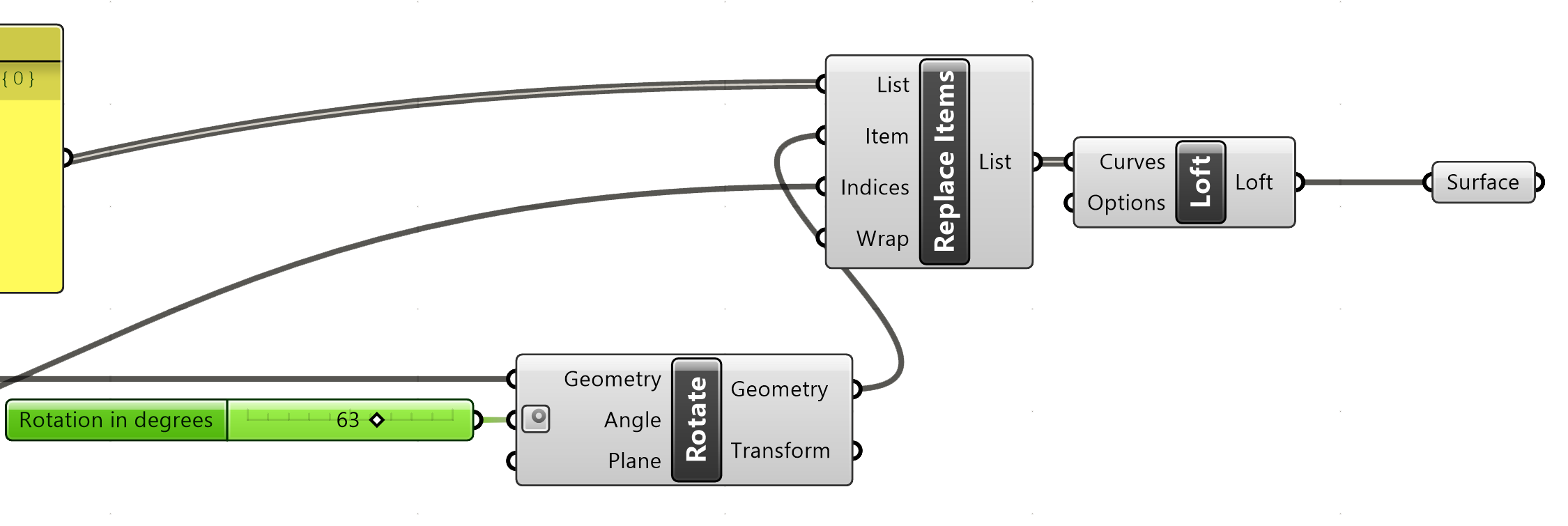
For good practice, always add a parameter at the end and rename your sliders.
Add a final surface parameter
Creating surfaces in Grasshopper 3/5
Sweep 1 Raillink copied
For Sweep 1 Rail we need a curve for the rail and 1 or more curves as sections. The setup is quite simple. We create two Curve parameters. One for the rail curve and one for the section curve.
Sweep 1 rail
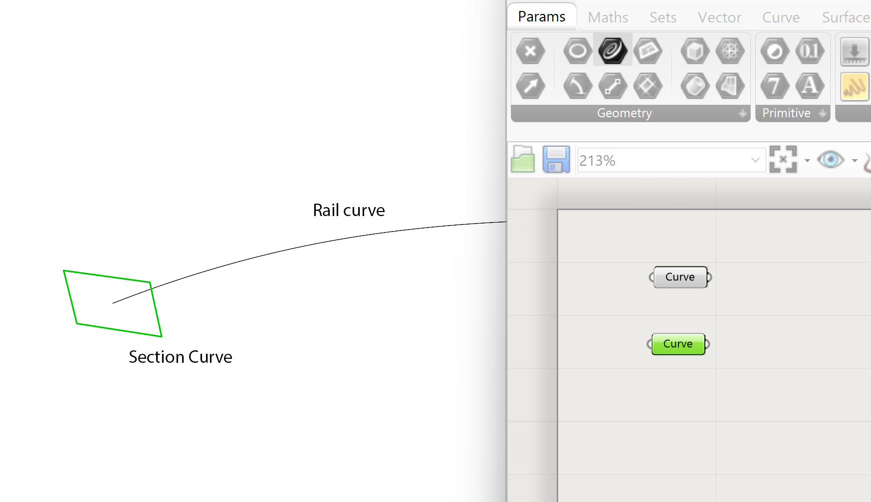
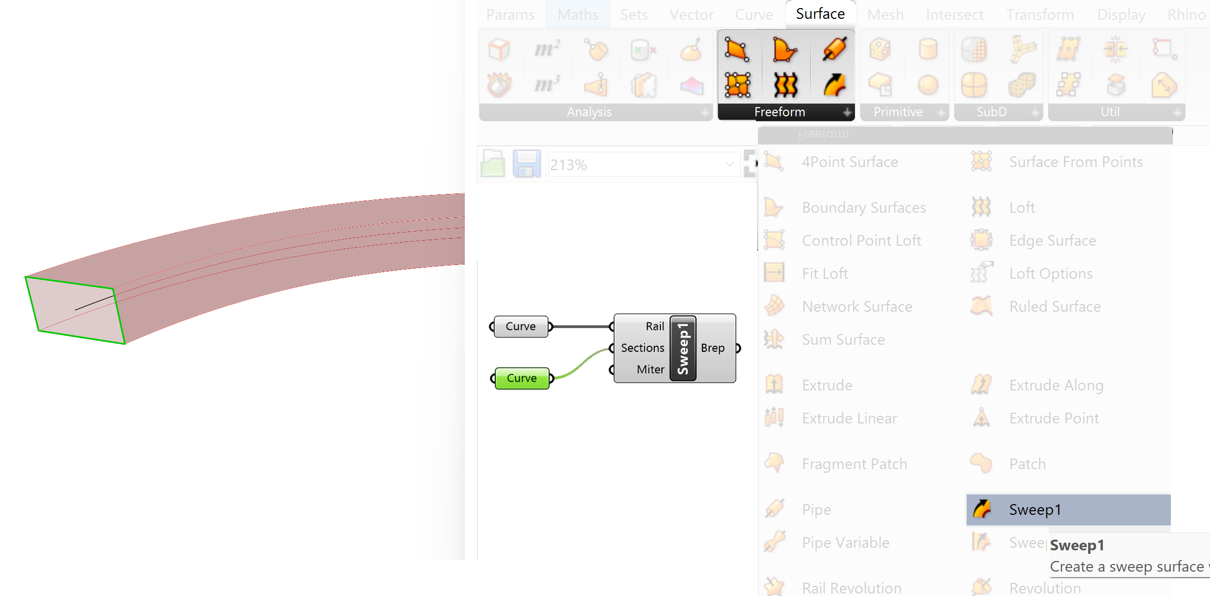
The sweep 1 rail component resides under the
Connect the output of the Curve parameter with the rail connected to the rail input of the Sweep1 component.
Connect the output of the Curve parameter with the section connected to the section input of the Sweep 1 component.
Sweep 1 component
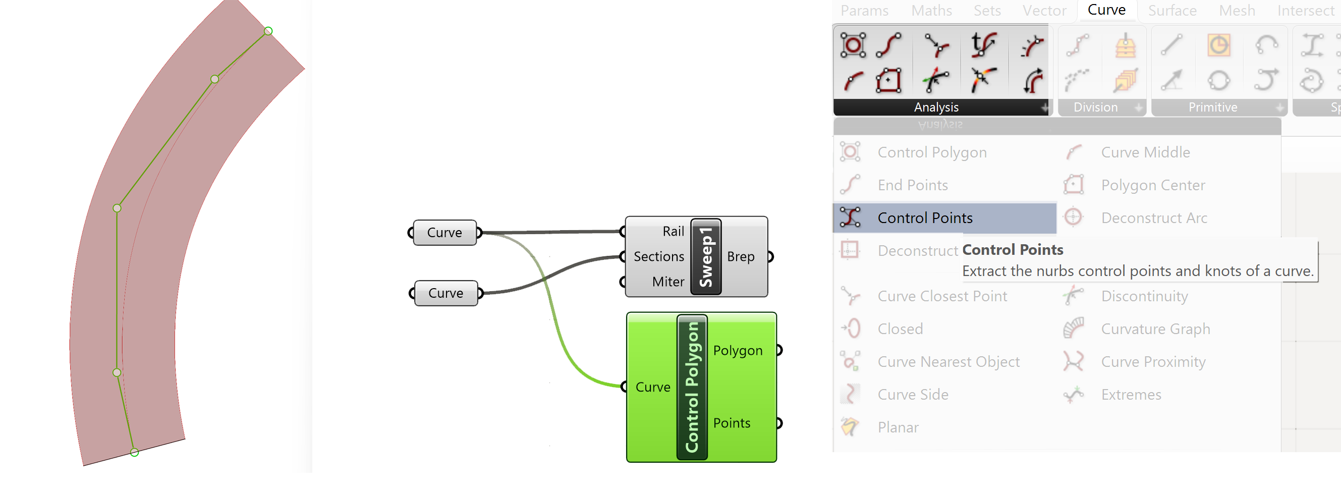
To make the rail adjustable within Grasshopper we need to move one or more Control Points (CP) of the rail curve. We will extract the CP’s from the Rhino curve, select one or more CP’s and move them. The moved CP’s will then be integrated back in the original lists of CP’s of the Rhino rail curve.
Extracting CP’s from Rail
From the list of CP’s we select two CP’s we want to change.
- Attach a Panel to the output Points of the Control Polygon component. This will show the list of how many CP’s the rail is constructed of.
- With “List Item” we select the points from the list we want to change. In this case we select 2 CP’s
- For selecting the items from the list we attach in this case two number sliders to the index input of the List Item component. With Shift pressed on your keyboard you can drag multiple outputs in a single input.
Selecting CP’s to Move
The next step is to move the selected CP’s
Go to
The move component needs two inputs, the CP’s which we want to move and the direction and distance of the movement.
To define the motion we use two
and couple a series of number sliders to the X,Y and Z component input. The number sliders define the amount of movement.
Both outputs of the Vector XYZ can now be connected to the motion input of the Move component (Shift Drag). Be aware that the order of connection will dictate, or the value is used for the first CP in the list or the second. The first connected will align with the first CP in the list of the List Item component.
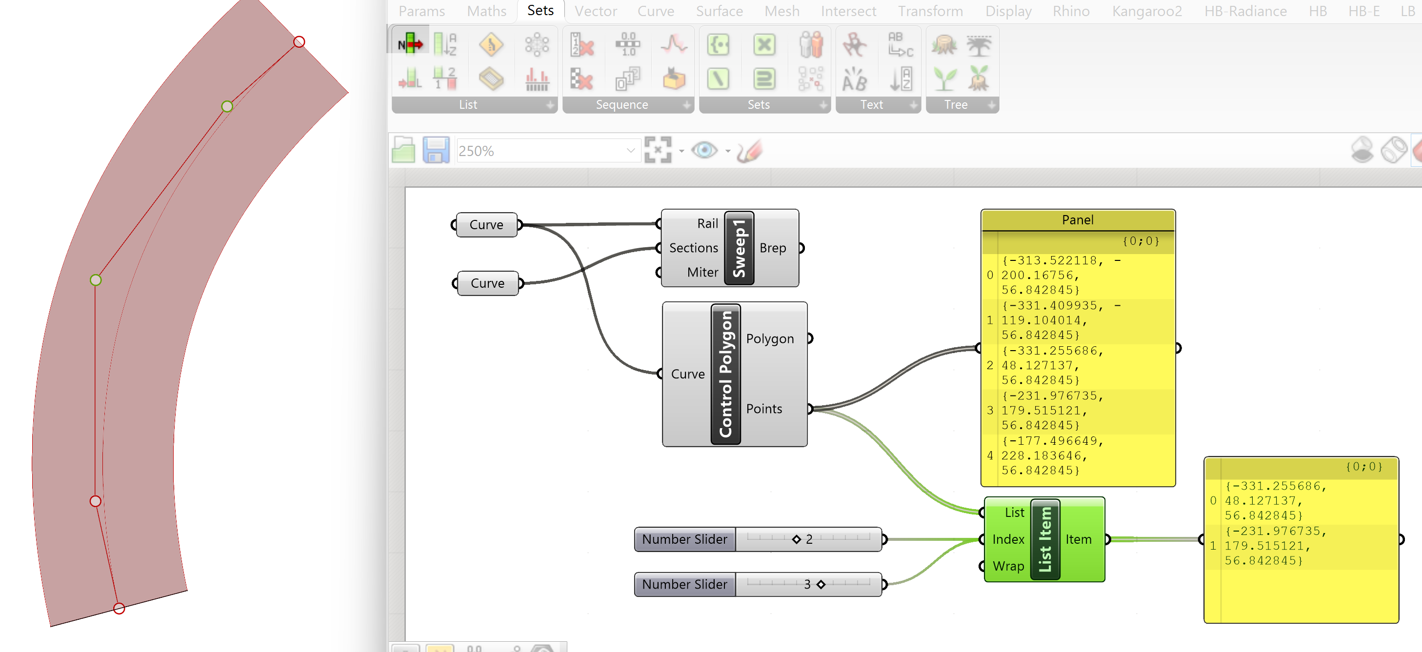
Move of multiple CP’s (Control Points)
To change the rail, we have to integrate the moved CP’s into the original list and rebuild the Rail with the new moved CP’s
- Go to replace Item
Replace item has several inputs. The list input is connected to the Points output of the Control Polygon component. This is the original list of CP’s of the rail. In the Item input we connect the moved CP’s output of the Move component. The indices input refers to which points in the original list have been changed. In this case we can use the Number sliders of the List Item component. These were used to select the points we wanted to move from the original list. Couple these number sliders with Shift drag both to the indices Input of the Replace Item component. We have now a list of points with the original points and the replaced moveable points.

- We can connect the output of the Replace Item Component to a Nurbs Curve. This will result in a new rail.
- The last step is to connect the output of the NURBS Curve to the Rail input of the Sweep 1 component. The Sweep 1 rail will be rebuilt with the new Control Points.
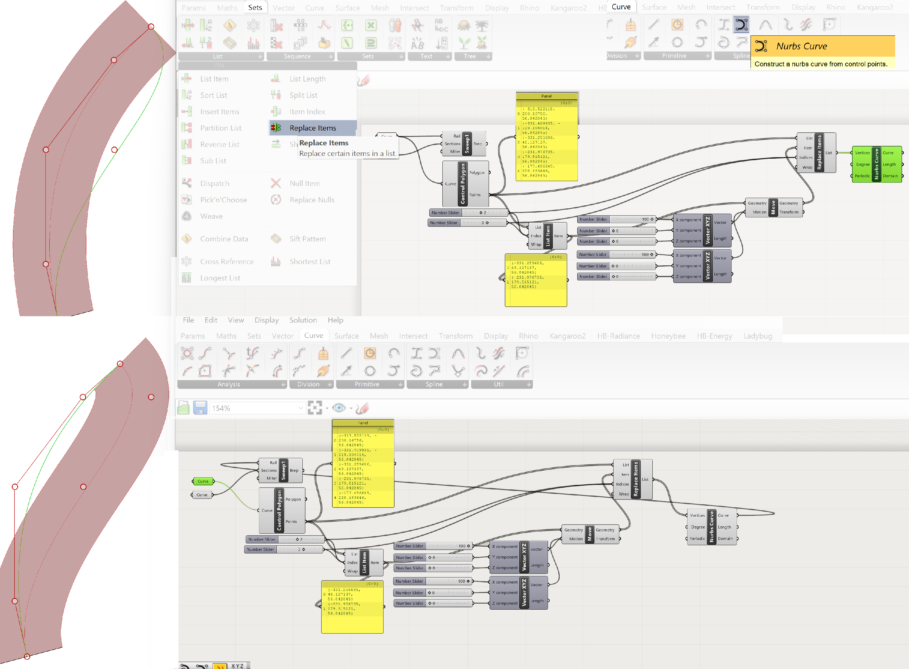

Creating surfaces in Grasshopper 4/5
Patchlink copied
The Patch option looks like the Planar option however the Patch option also supports nonplanar curves for generating a surface. If we have a set of curves which form a closed set of curves, they can be the basis for a surface.
- Select the curves or a single closed curve and connect them with a Parameter>> Curve to Grasshopper
- To construct the surface, we select the “Patch”:
- Connect the Curve output to the Curves Input of the patch component.
You can change the curve in the same way as the Sweep 1 rail. Please check out this example. This works best if the curve is a single closed curve. The patch will deform accordingly.
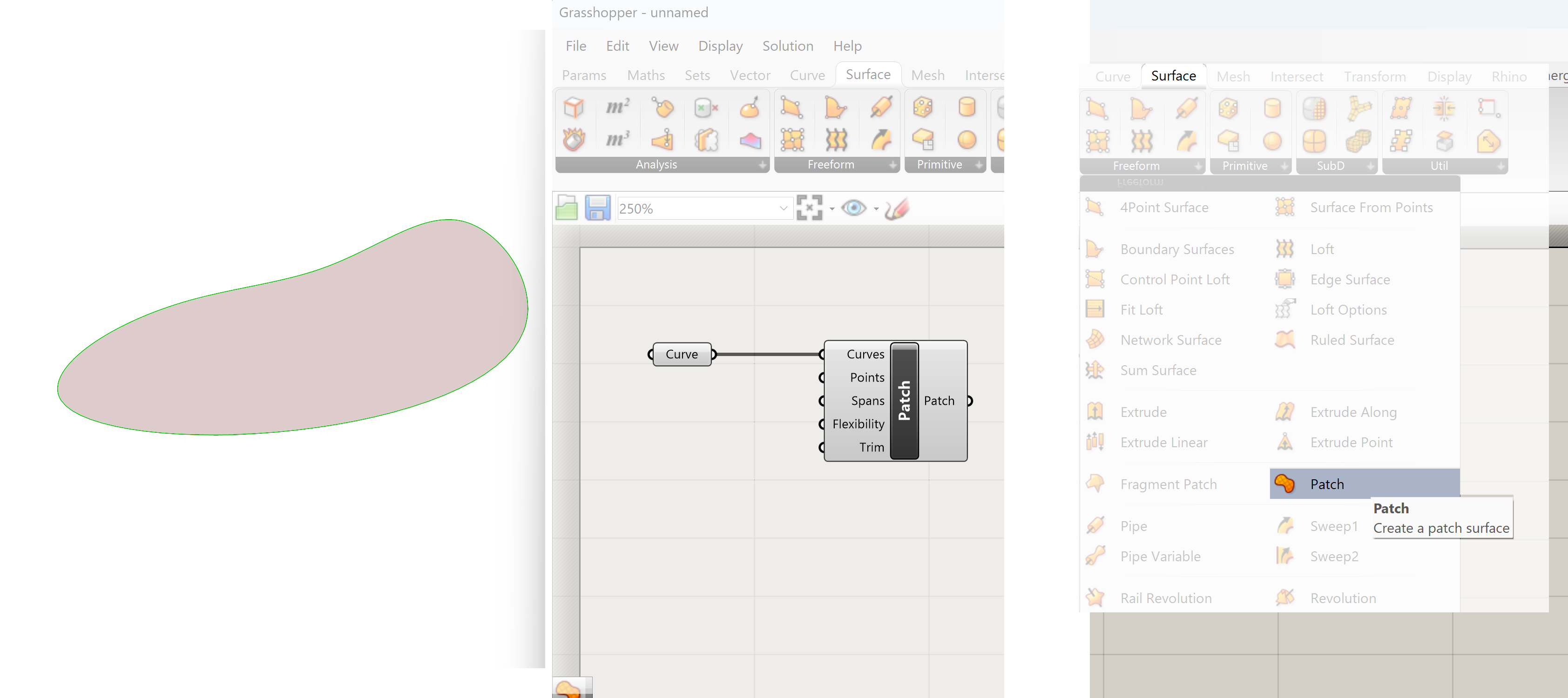
Creating surfaces in Grasshopper 5/5
Conclusionlink copied
Creating surfaces in Grasshopper is quite straight forward. If the curves are created and adjusted in Rhino, the network will be simple. Altering the curves in Grasshopper to alter the surface is an effective option. This increases the complexity of the Grasshopper network however add substantially to its flexibility.
Write your feedback.
Write your feedback on "Creating surfaces in Grasshopper"".
If you're providing a specific feedback to a part of the chapter, mention which part (text, image, or video) that you have specific feedback for."Thank your for your feedback.
Your feedback has been submitted successfully and is now awaiting review. We appreciate your input and will ensure it aligns with our guidelines before it’s published.
