Brick Wall
-
Intro
-
Design
-
Creating a cosine curve
-
Defining the location and rotation planes for the bricks
-
Populating the bricks
-
Adding Edge Half Bricks
-
Conclusion
Information
| Primary software used | Grasshopper |
| Course | Brick Wall |
| Primary subject | Parametric Modeling |
| Secondary subject | General |
| Level | Advanced |
| Last updated | June 5, 2025 |
| Keywords |
Responsible
| Teachers | |
| Faculty |
Brick Wall 0/6
Brick Wall
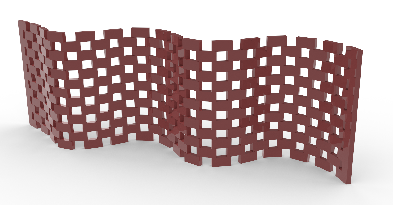
This tutorial teaches creating a curved brick wall using a stretcher bond pattern, mathematical functions, and the dispatch function.
This tutorial will be about creating a curved brick wall using a ‘stretcher bond’ brick pattern that consists of bricks of the same size laid from the mid of each brick above and below. In this tutorial you will use mathematical functions to generate the wall and will use the dispatch function to achieve the ‘stretcher bond’ pattern.
Brick Wall 1/6
Designlink copied
As said before, the task of this tutorial is to make a curve brick will with a ‘stretcher bond’ brick pattern. The variables of the definition will be:
- the wall length = 15 meters
- the wall height = 5 meters
- the brick length = 0.4 meters
- the brick height = 0.2 meters
- the horizontal distances between the bricks = 0.2 meters = 50%
- the vertical distances between the bricks = 0.4 meters
Brick Wall 2/6
Creating a cosine curvelink copied
The first step we’ll do is generate the basic curve shape of the wall with a cosine function is to define the range for the cosine curve. We can do that be create inputs for a domain range using Construct Domain and Range components. In this example, the wall length will be 15 meters, and a precision of 10.

- Define the domain with a Construct Domain component
- Define the wall length by connecting a Number Slider to the Domain End inputs
- Create a Range
- Define the precision with a Number Slider as step input to the range
Next, we make a list of points with the cosine function. These points will be used to construct the curve.
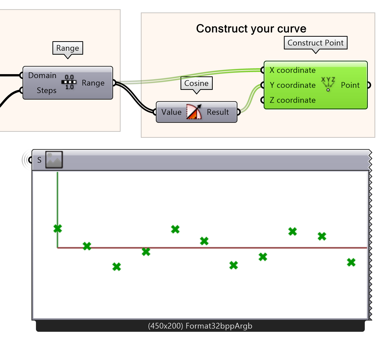
- Add a cosine component to the canvas
- Construct a new point
- Connect the Range output to the Cosine and to the X coordinate input Construct Point
- Connect the Cosine function to the Y input of a Construct Point node.
The created point will be translated in an interpolated curve. This results in the basic curve that will be used to define the shape of the wall. Play around with the input values of wall length and precision and see how the curve changes.
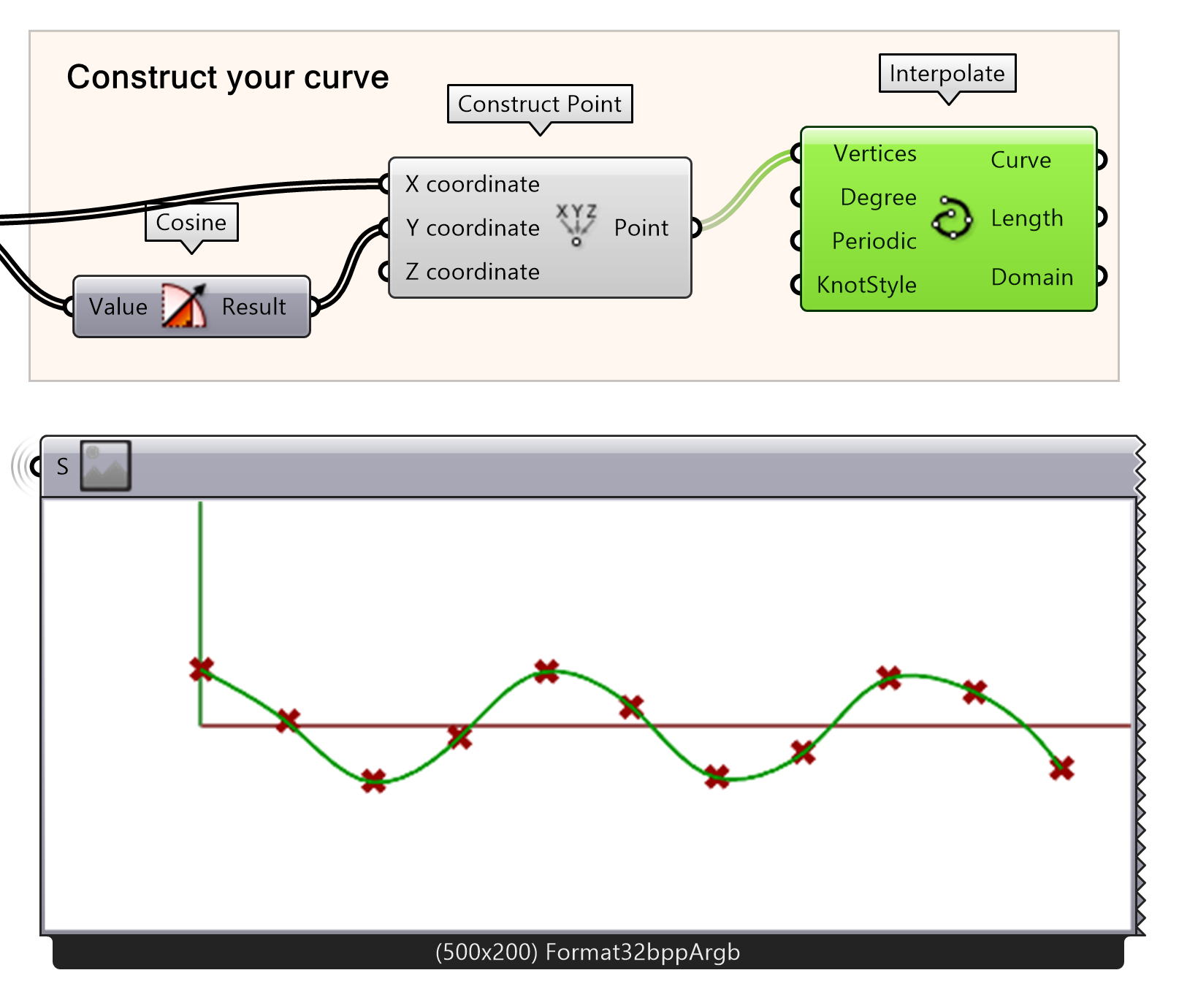
- Create a curve from the points
- Connect the Construct Point outputs to the Vertices input for Interpolate component.
Brick Wall 3/6
Defining the location and rotation planes for the brickslink copied
We will use the cosine curve from the previous step and divide this with a preset distance between each division point. This distance will be related to the distance between the center of each brick. The first thing we do this step is creating a series of vertical lines. The height of these lines will be our height of the wall. The cosine curve will be divided with the ‘Divide distance’ component.
Before we divide the curve, let’s set a bound constraint for the brick size by constructing a domain. The distance between the bricks depends on the length of the brick, as to stack a wall the bricks should be able to be placed on top of each other. Therefore, the domain will be set on a minimum of the brick length, meaning no space between the bricks, and to twice the brick length, meaning that exactly one brick can be placed in between the bricks. To control the distance between the bricks a remap of the values is used together with a slider from 0 to 1. In this example, a brick length of 0.4 meter and a distance of 50% is used, meaning that the space between the bricks is half a brick length (0.2 meters).
- Make a slider for ‘Brick Length [m]’
- Multiply by 2
- Using construct domain add the inputs from the brick length and the multiplied value.
- Create a slider ‘X Distance [%]’ from 0.00 to 1.00
- Control the brick spacing by remapping the values using the number slider input and the Domain as target.

Note: Make sure to set the minimum value of the brick length to a representative value. Setting the brick length to 0.00 meters could result in accidentally crashing your file.
Now that the distance between the bricks can be set parametrically correct, the next step is to divide the curve accordingly. The cosine curve can be divided into smaller distances with divide distance by inputting the remapped value of spacing.
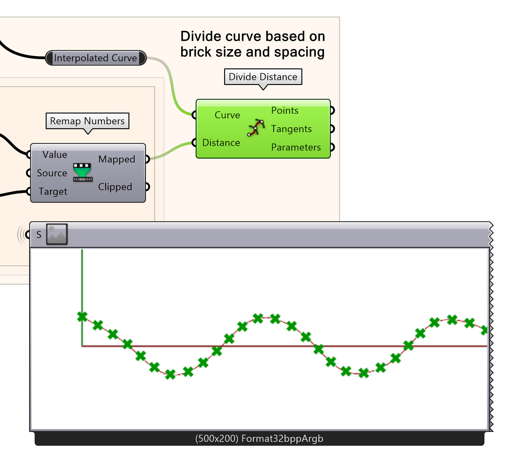
- Divide the cosine curve into smaller distances by inputting the mapped number from the Remap Numbers component.
In the next few steps, we will use the tangents of the curve to define the directions of the bricks. You can visualize them using the Vector Display component. If the Vector arrows are not visible, you can make them larger by right-clicking on the Vector Display icon and setting a default size in the arrow tab.
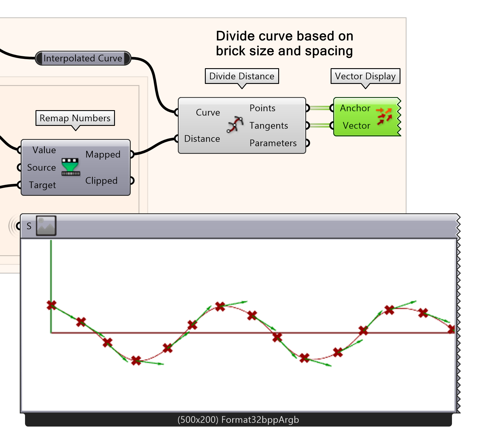
- Visualize the tangents using Vector Display
- Connect the points output of divide distance to input anchor
- Connect the tangents output of divide distance to input vector
Now we will create vertical lines to define the wall height using the divided points as Start. In this example, a wall height of 5 meters is used.
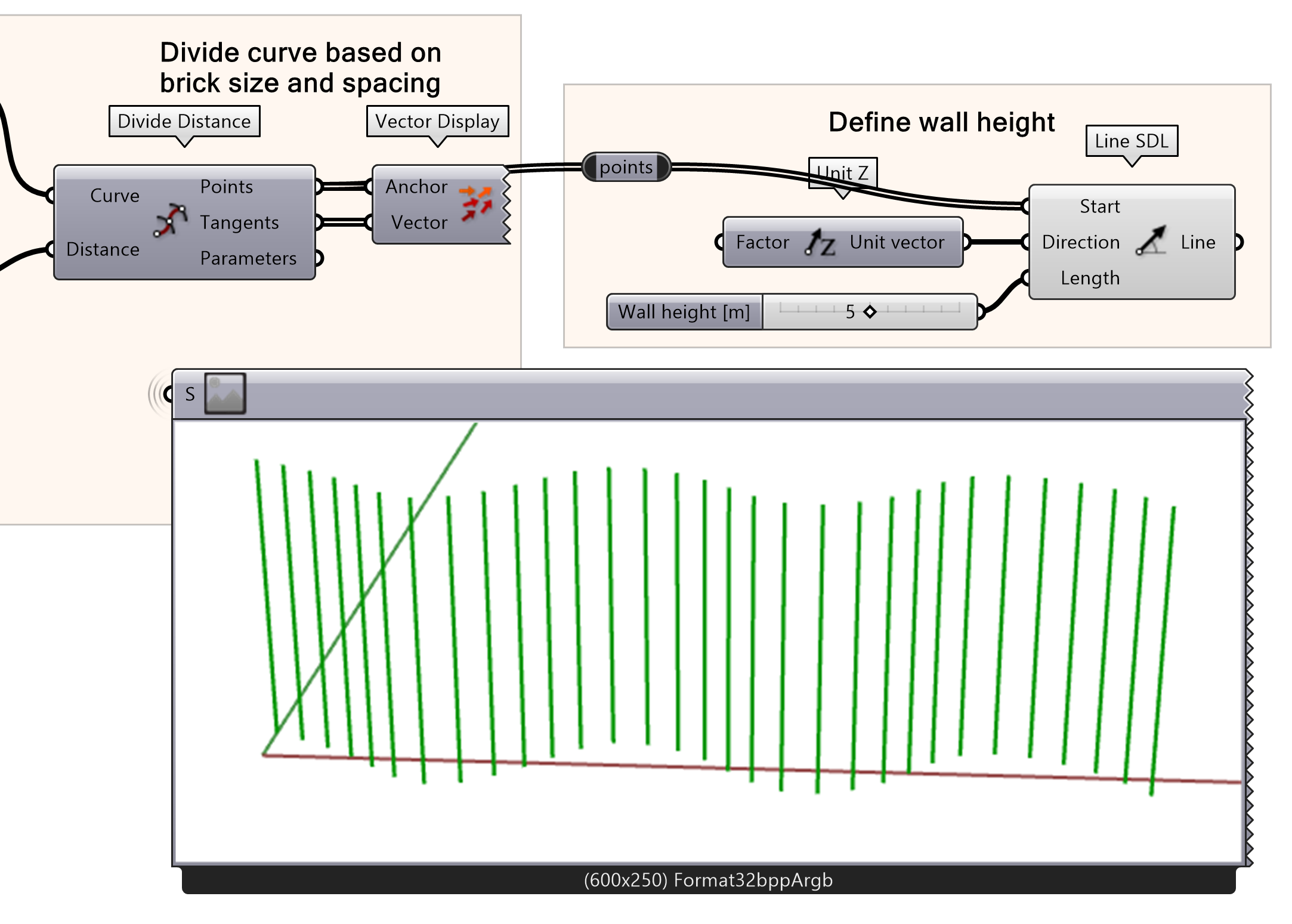
- Connect the Divide Distance Points output to a Line SDL
- Define the Direction with a Z Unit vector
- Specify a Length using a Number Slider
We can now divide the curve with points to get the center point for each brick along the vertical axis. To do so, we divide the individual lines again using the Divide Distance component. The vertical division parameter will define the vertical distance between the center of each brick. To create a correct parametric wall, the vertical distance will be twice the brick height. In this example, the brick height is 0.2 meters, therefore the vertical distance between the bricks is 0.4 meters.
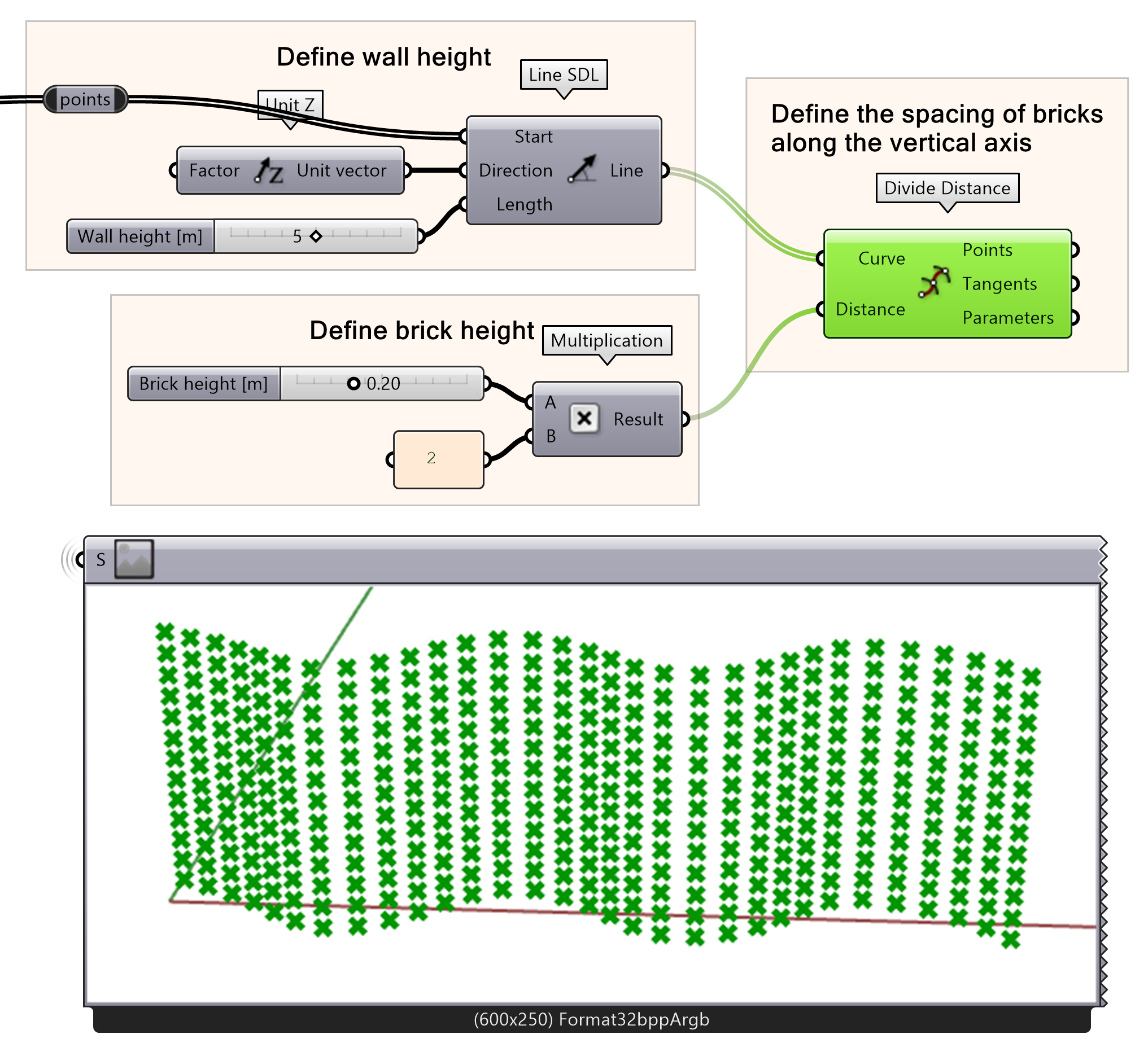
- Connect the Line output to a Divide Distance Curve input.
- Define the brick height using number slider for ‘Brick height [m]’.
- Define vertical brick spacing by multiplying the brick height by 2 using a multiplication component.
- Connect the multiplication results into the Distance input for Divide distance component.
Now that all the placement point for the pricks are created, the next thing is to find the direction of the planes. The pricks will be placed based on the direction of the planes, and these direction needs to be adjusted so the bricks follow the direction of the curve. First, a horizontal plane for each point will be created.
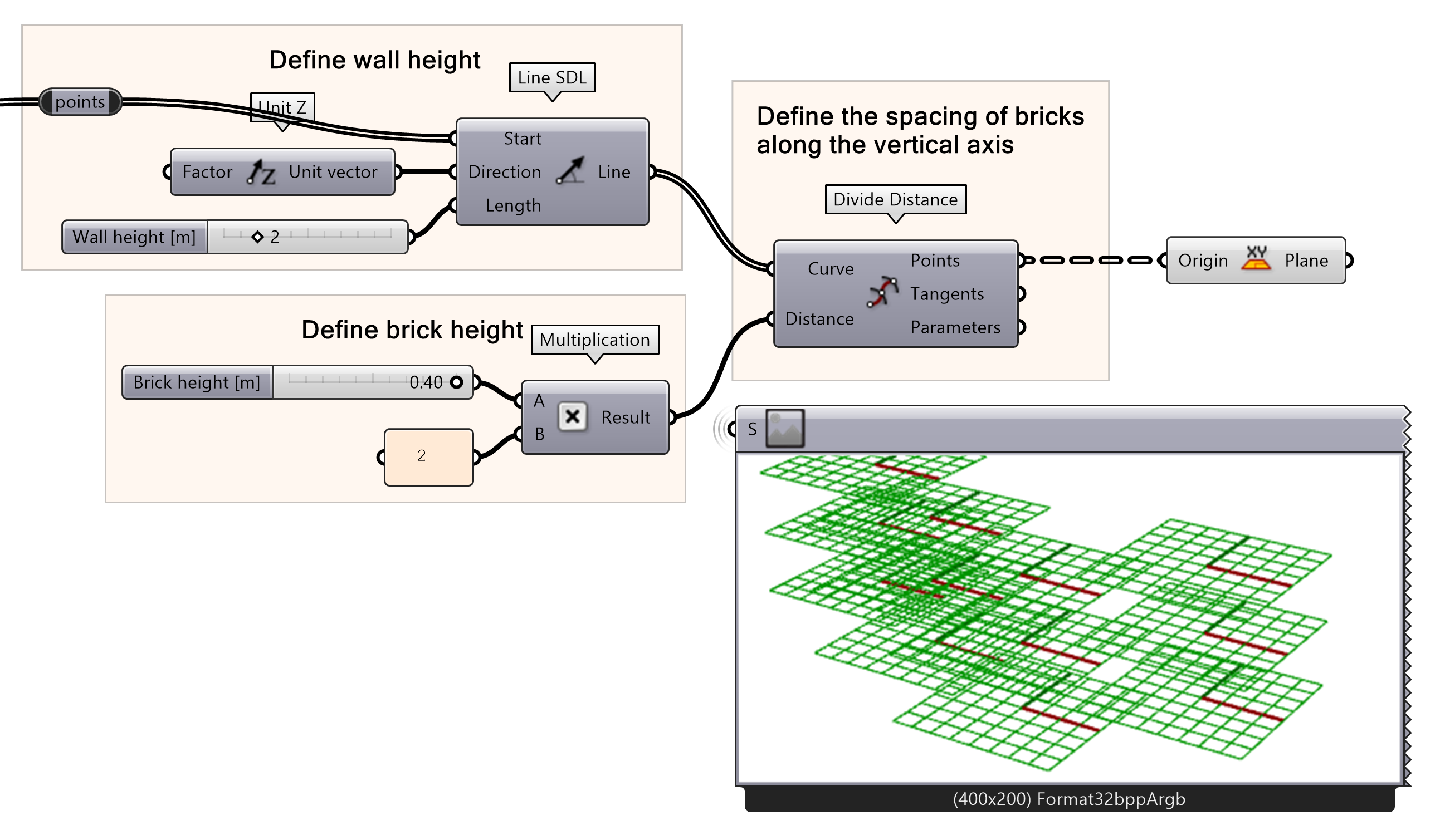
- Create a horizontal plane from the division points
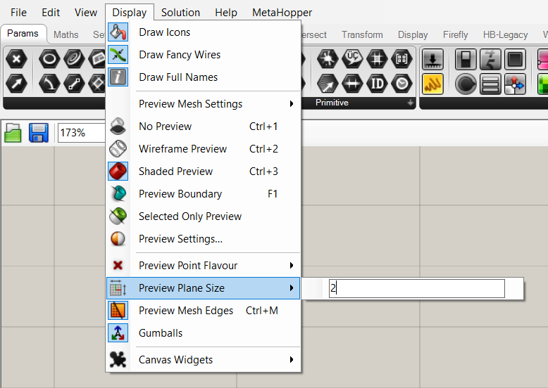
With the planes, the direction of the points are shown. If the planes are too big or small, you can change the settings in the display tab of Grasshopper. This does not influence the outcome of the script, but only changes the visuals.
Before continuing, we first need to flip the data. By flipping the data, the structure changes. Now the data is not structured per origin point of the original curve we created but based on the height. Therefore, we can use the ‘Flip Matrix’ component. Feel free to connect some panels to find out how it works!
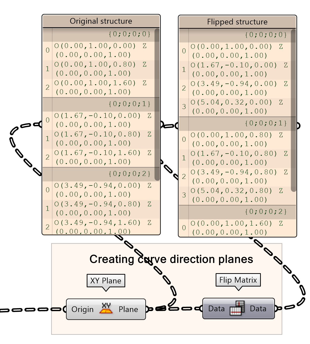
- Flip the Plane output matrix
If you want to know more about flip matrix and the basics of data trees, you can follow the ‘Basic tree actions’ tutorial.
The current planes don’t follow the direction of the curve. To align the directions of the planes with the direction of the curve, we connect the flipped data to the input of an Align Plane component. The direction is based on the Tangents we found in the first Divide Distance outputs.
- Add an Align Plane component to the canvas
- Connect the Data output to the Plane input
- Connect the first Tangents output to the Direction input

Brick Wall 4/6
Populating the brickslink copied
Last step is populating the bricks according to the planes. We use a ‘Center Box’ component that will use the aligned planes as a basis to generate the bricks. But before we do this, we have to achieve the ‘stretcher bond’ brick pattern. We will use a ‘Dispatch’ to get this result.
The ‘Dispatch’ component tests a list of data according to a true or false pattern. The true values will be listed in the A output and the false values in the B output. Before we use the dispatch function, we have to flip the matrix of the Plane output of the ‘Align Plane’ component from step two. By flipping the matrix we will be able to select alternating horizontal lines, instead of alternating vertical lines. Connect the output of this flipped matrix to the List input of a dispatch function. Since the internalized pattern of the dispatch already is correct and set on 0, 1, we don’t have to add any input. You see that you can now select each alternating horizontal line separately.
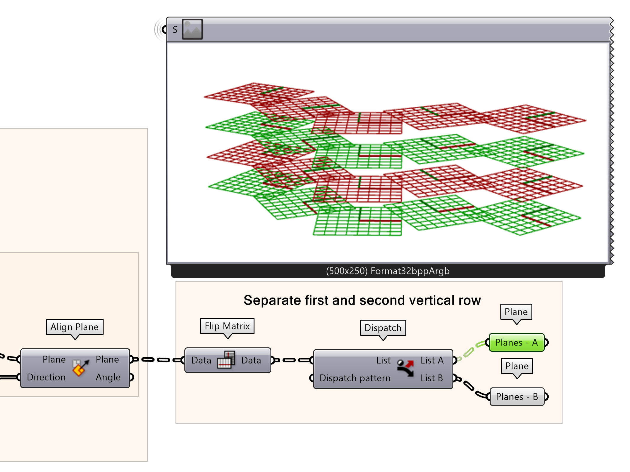
- Connect a Flip Matrix‘s input component to the Align Plane output
- Dispatch the Data
Next, we want to select horizontally alternating planes. To do so, first the output A and B from the dispatch need to be flipped. By flipping the matrix you can start selecting horizontal planes alternating with dispatch. For list A, select the list A again of the second dispatch. For list B, select the list B again of the second dispatch. This will give the alternating pattern of the ‘stretcher bond’ pattern.
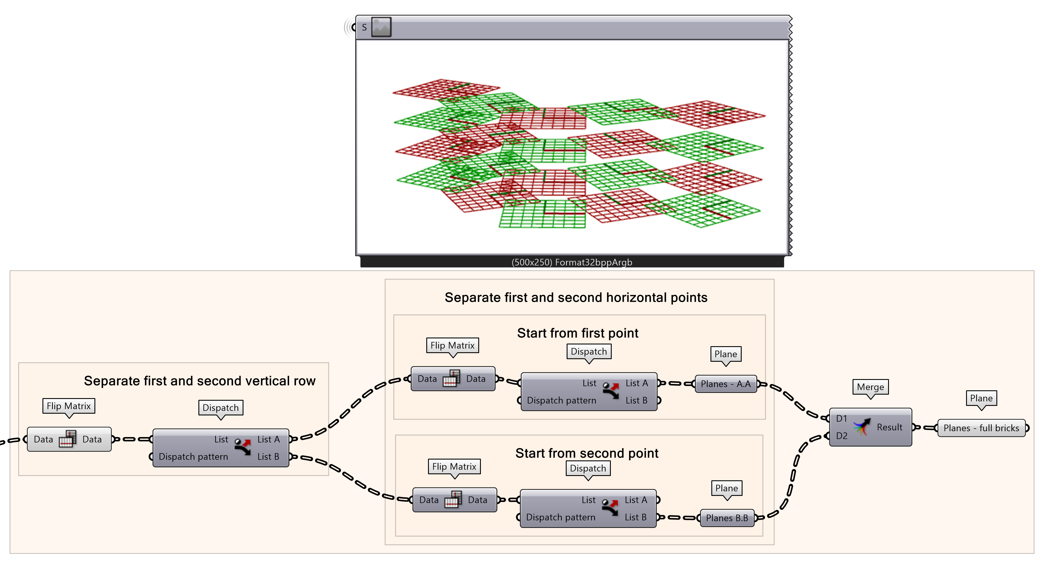
- Connect a new Flip Matrix component to the List A and List B output
- Dispatch the Data outputs
- For list A, select the first dispatch output. For list B, select the second dispatch output.
- Merge selected planes with
Now that the planes are in the right direction and pattern we can generate the bricks with the center box component. First, create a centre box component and input the full brick planes in base. Then, define the depth of the bricks and connect the brick length and height as defined in earlier steps. You will see brick shaped boxes populated according to the planes and you finished your ‘Stretcher bond’ cosine wall.
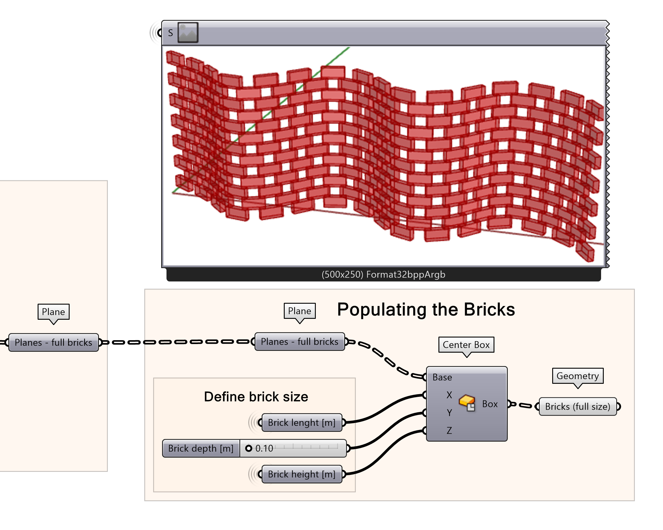
- Create a Center Box from planes merge output
- Define ‘Brick depth [m] with a Number Slider
- Connect the brick height and brick width from the earlier steps
- Connect the Box outputs to a Geometry parameter
This creates a brick wall in ‘Stretcher bond’. However, as you see, on the edge of the wall the wall is missing bricks which create a nice, finished wall. One final step in the script should be added to add the end condition bricks which will be half the brick size to make this into a complete wall.
Brick Wall 5/6
Adding Edge Half Brickslink copied
To complete the edges of the bricks with ‘corner bricks’, we must create the planes necessary and add a brick size that will fit in the end condition. This process starts by defining the brick size by taking the ‘brick length’ and dividing it by 2 which is the correct size to fill in the end gaps created by the brick plane offsets. Before we get started, let’s select the planes that we will be using to work with our script by creating a data component for each plane from the Dispatch components outputs.
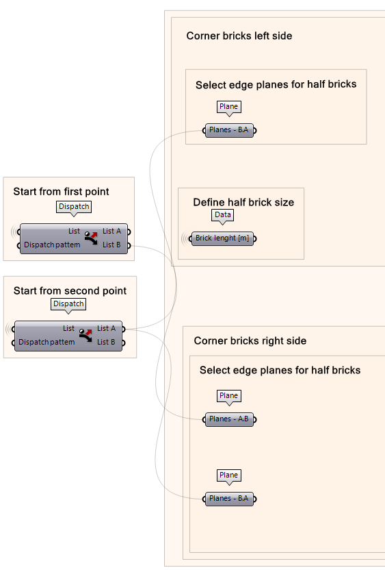
- Create data components for each input we need to create the edges bricks.
- From the dispatch components, create ‘Plane B-A’, ‘Plane A-B’, and ‘Plane B-A’ data components as shown in the illustration.
- You will also need to have the input for ‘Brick Length [m]’ into a Data component which will be used later on.
- Once you have all your data component as inputs, you can right-click on them and make the wire display to “hidden”.
Selecting the ‘Left’ Edge Planes
We will start by generating the edge bricks on the left side first. The process starts by defining the brick size that will be placed in the edge condition and the planes where those bricks will be generated.
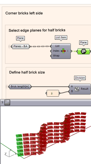
- Using a List item component, plug the ‘Planes B-A’ data into the list input to select the first (0) index from the planes list. The index is set to zero by default.
- You will also need to specify the brick size by taking the ‘Brick length [m]’ and dividing it by two to get the half brick size using the division component.
- You can use a panel and insert the value ‘2’.
Moving the ‘Left’ Edge Brick Planes
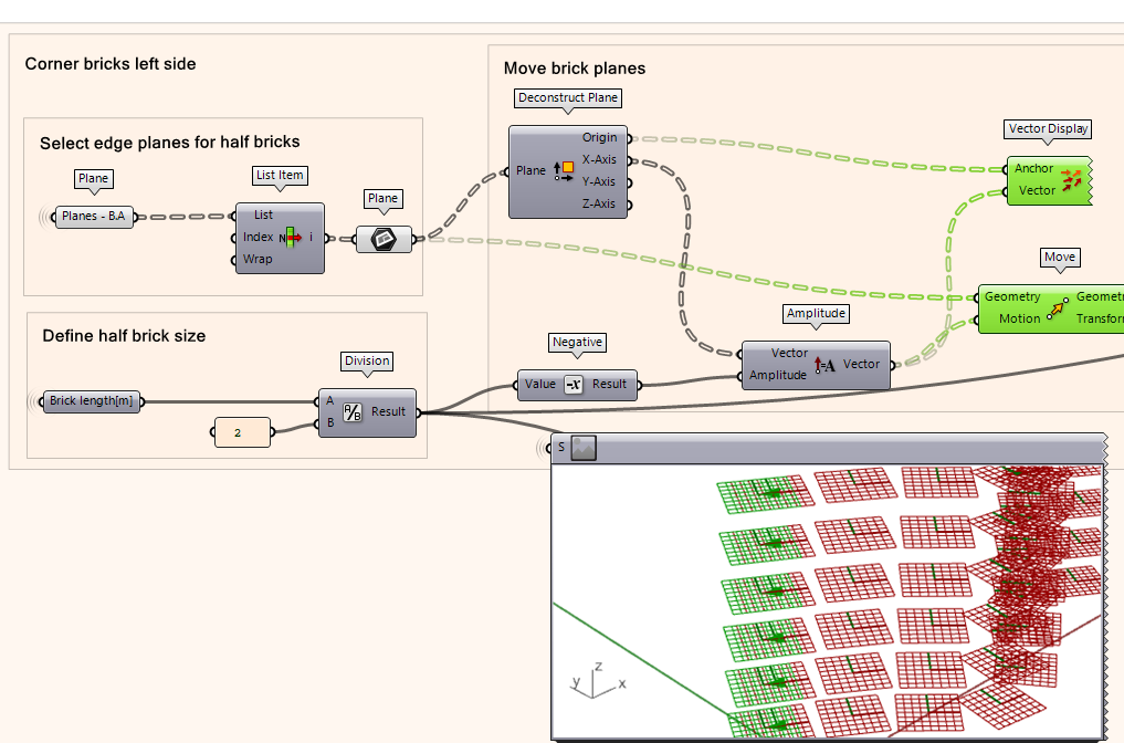
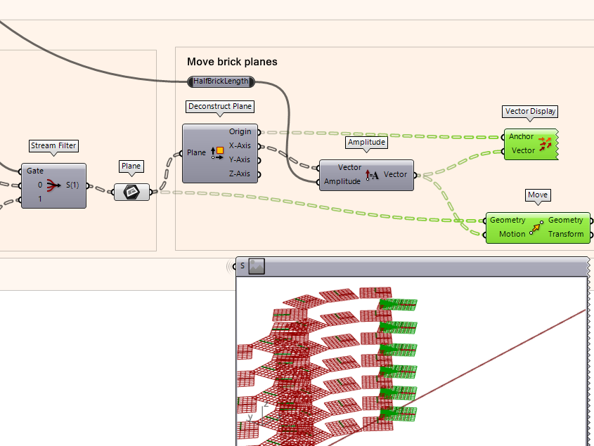
Once you have your planes, we then need to move the planes by a half-brick size distance away from the wall.
- To create the motion vector, first use the deconstruct plane component to extract the ‘X’ direction of the plane. This gives us the X direction with respect to the plane.
- Next, take the X-Axis output and plug it into the ‘Vector’ input of Amplitude component which takes the X vector of the plane.
- The amount of movement will be the half-brick size but first convert it to a negative value by using the Negative component. This will ensure it is moving away from the brick wall.
- Use a Move component where the input is the actual plane we want to move and the motion is the Amplitude output which already contains the amount of units it needs to move by and the vector direction of movement.
- To check the direction vector is correct, use a Vector component where the origin of Deconstruct Plane is the ‘Anchor’ and the Amplitude is the ‘Vector’.
Selecting the ‘Right’ Edge Planes
We now work on the corner bricks on the right side. The process will start by isolating the planes needed to generate the edge bricks, similar to the previous step. We take the inputs of ‘Plane A-B’ and ‘Plane B-A’, then we deconstruct the plane like and move it along a vector direction.
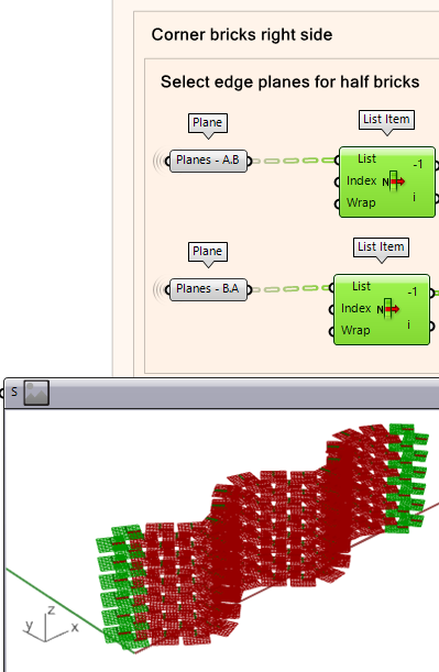
- First, take the last item of the list in the planes list. This can be done using a List Item component. You can get the last item of the list by adding the -1 index of the list (see next note with illustration for how to do it).
- You will need to take the planes from the -1 output to proceed to the next step.
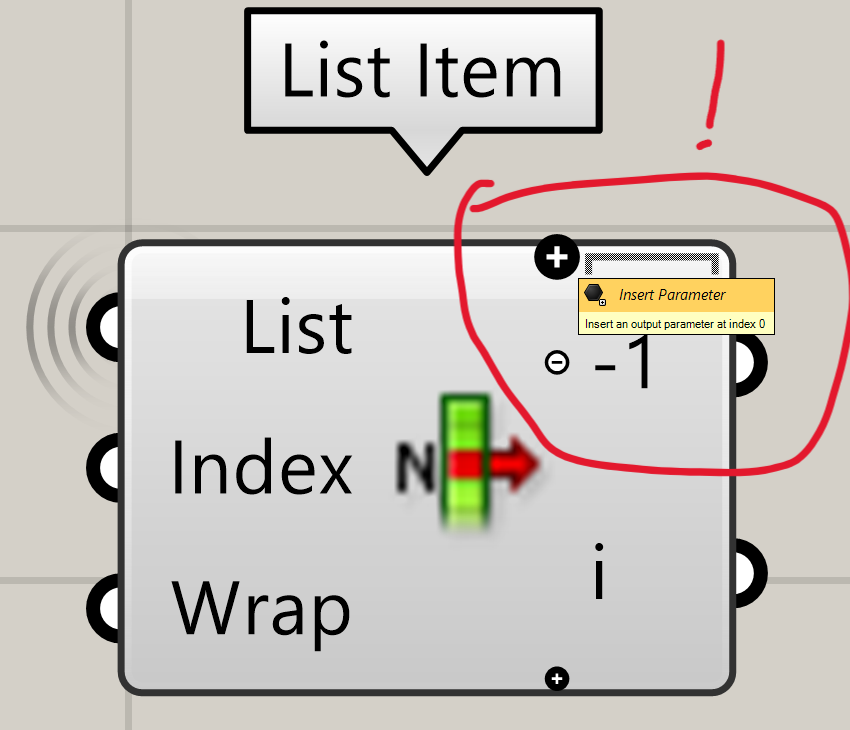
Tip: to select the last item of a list using the List Item component, zoom in very close to the component until you see a “+” sign appear. You can add an output by clicking on the plus sign on the top of the component, this will give you the list item index minus a number. And clicking on the bottom one gives you a +1 index.
Next, you will select the first item from the list to deconstruct its plane and retrieve the origin point of the planes.
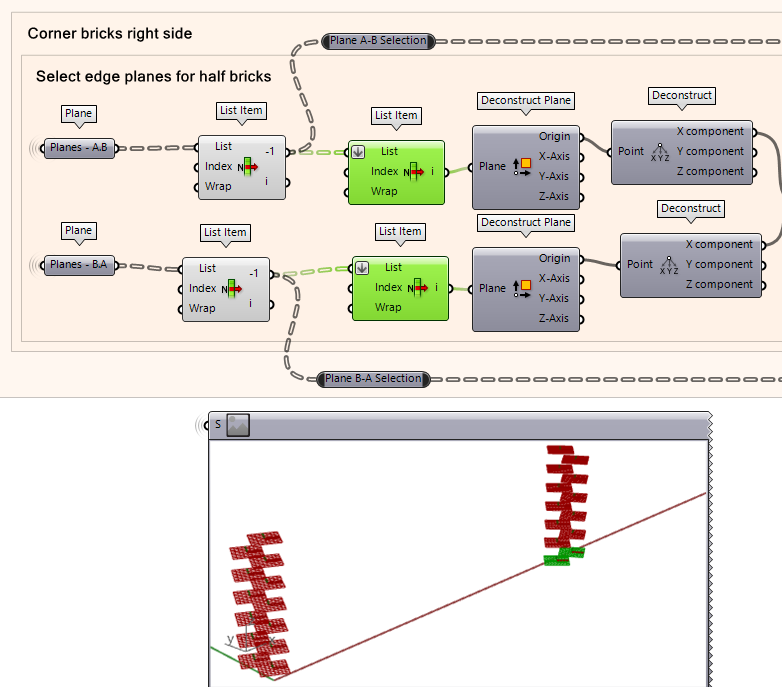
- Using List item, select first (0th) item of the list for both plane lists.
- Next, retrieve the origin point of the planes using Deconstruct Plane. This will give the ‘Origin’ output.
- Plot a point on the origin coordinates using Deconstruct We will take the ‘X’ component of the coordinates for our next step.
Now that we have the X-coordinate of the plane origin point for both planes, we proceed to the following step. The reason we select both planes is because sometimes the edge plane is on the bottom plane and sometimes it is on the plane above. In other words, we need to make sure we select the planes that is on the most outer edge of the brick wall. If we compare the X coordinate values for both planes, we can then determine which plane exists on the most outer plane of the wall’s edge. To do this, we need to compare the values of X-coordinates of both planes and allowing the planes positioned at the most outer edge to be selected.
- Using the Larger than component, plug the two X Component outputs for the origin points of the planes. This will tell us which when ‘Plane B-A’ is larger than Plane ‘A-B. The output will be either Ture or False.
- Next, we use the Stream Filter component where the index of the gate stream corresponds to the True or False statement. Meaning, if the statement is True, it allows ‘Plane A-B’. Otherwise, it goes to ‘Plane B-A’.
- You can now see in this selection that the gate 0 (True) was outputted as the planes on the right side.
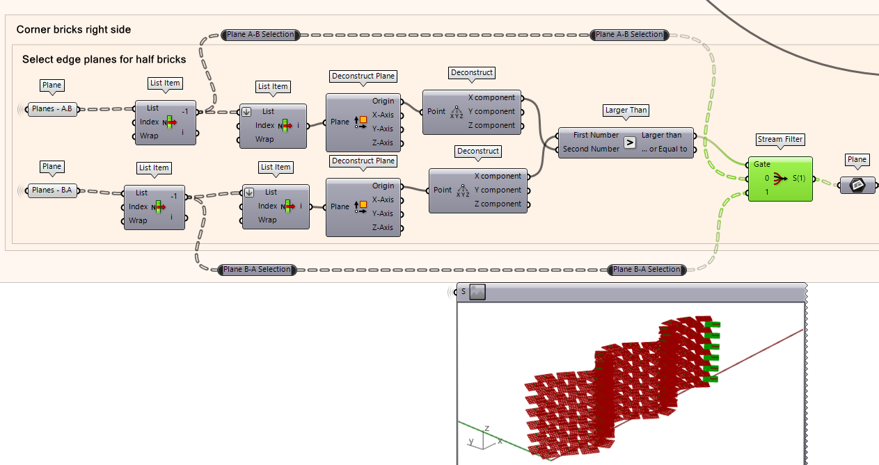
Moving the ‘Right’ Edge Planes
Now we move the outer-most planes by the half-brick amount similar to the opposite side. We
- Extract the X-axis of the planes’ vector direction using the component using the Deconstruct plane component. This gives us the X direction with respect to the plane.
- Next, take the X-Axis output and plug it into the ‘Vector’ input of Amplitude component which takes the X vector of the plane. This time instead of taking the negative value, we take the positive value of the distance which will move the plane in the opposite direction of the planes on the opposite side of the brick wall.
- Use a Move component where the input is the actual plane we want to move and the motion is the Amplitude output which already contains the amount of units it needs to move by and the vector direction of movement.
- To check the direction vector is correct, use a Vector component where the origin of Deconstruct Plane is the ‘Anchor’ and the Amplitude is the ‘Vector’.
Combining the Bricks
Now we generate the half bricks at the edge condition of the wall using the moved planes we have created. The base of the bricks will be the planes, and the half-brick length will be an input, as well as the normal brick height and depth.
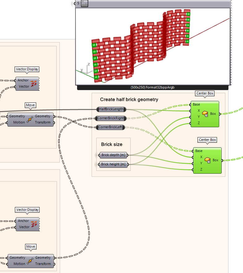
- Using the Center Box component, plug each of the two moved planes into a separate Center Box component.
- Plug the half-brick size into the X input which will generate a box the size of a half brick in length.
- Next, retrieve the brick size established in the earlier script and plug the height in the Z input and the depth in the Y input.
- You should now be able to see the edge brick conditions filled with half bricks.
Visualize and render wall design
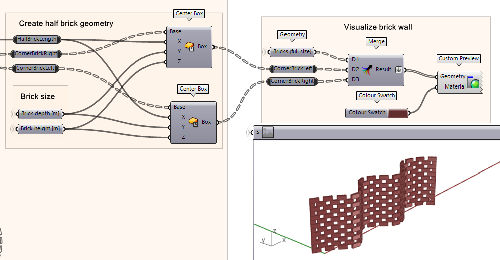
Finally, visualize the brick by selecting a color and a custom preview component.
- Using the Merge component, combine the outputs for the ‘brick full size’ and the two edge bricks we just created.
- Create a Custom Preview component and add a color using the Color Swatch component which then you can click on the color to adjust the hue, brightness, and saturation.
Brick Wall 6/6
Conclusionlink copied
Now you can utilize this script to make curved brick wall. Feel free to experiment with the curve and see what results you get.

Complete exercise file
Write your feedback.
Write your feedback on "Brick Wall"".
If you're providing a specific feedback to a part of the chapter, mention which part (text, image, or video) that you have specific feedback for."Thank your for your feedback.
Your feedback has been submitted successfully and is now awaiting review. We appreciate your input and will ensure it aligns with our guidelines before it’s published.
