Creating 2D Grids
-
Intro
-
Design
-
2D grid with series
-
2D grid with rectangular
-
Rhino geometry on grid
-
Parametric column on grid
-
Conclusion
-
Useful Links
Information
| Primary software used | Grasshopper |
| Course | Creating 2D Grids |
| Primary subject | Parametric Modeling |
| Secondary subject | General |
| Level | Beginner |
| Last updated | November 27, 2024 |
| Keywords |
Responsible
| Teacher | |
| Faculty |
Creating 2D Grids 0/7
Creating 2D Grids
Explanation of creating 2D grid using two different methods in Grasshopper.
This tutorial is divided into two parts. In the first part, you will learn how to create 2D grids using two different methods: using a series and move component and using the rectangle grid component. In the second part of this tutorial, you will learn multiple ways to design a column to be placed on the grid that was created in the first part.
Creating 2D Grids 1/7
Designlink copied
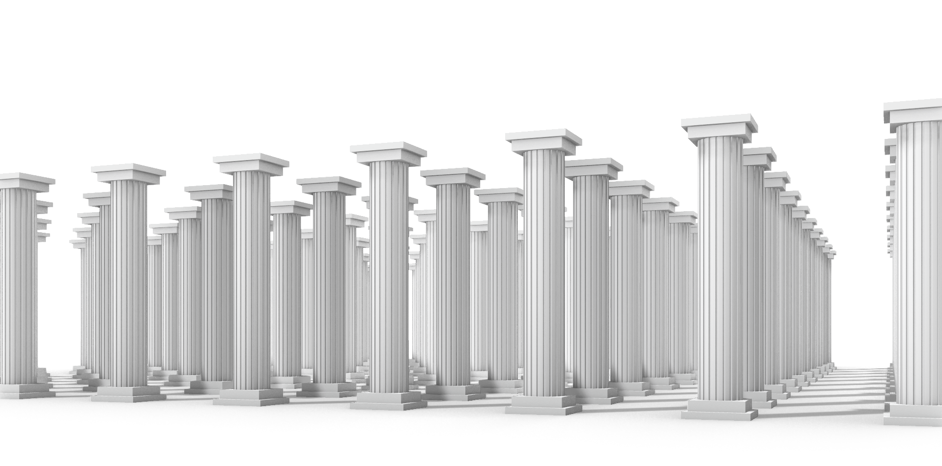
The task of this tutorial is to make a grid of round columns with the use of a point matrix. The variables of the definition will be:
- Grid of columns: 20×20 meters
- Distance between columns: 2 meters
- Height of the columns: 4 meters
- Diameter of the columns: 1 meter
Exercise file
Here you can download the Grasshopper file with the column geometry embedded to create the exact same design.
Creating 2D Grids 2/7
2D grid with serieslink copied
There are various ways to create 2D grids. In this method, a 2D grid is created using a series. First, a point is set according to the required location of the start of the grid. Then the point is copied according to the required number of points and distance between each one using a series.
Grid direction
To make the grid we start to defining the direction of the grid with 2 points. The origin of the grid is constructed with construct point (point from XYZ) node. The defaults coordinates of construct point are 0,0,0. These are used for this tutorial, if you want your grid to start somewhere else use sliders to define the X,Y and Z-coordinates of the start point of the grid.
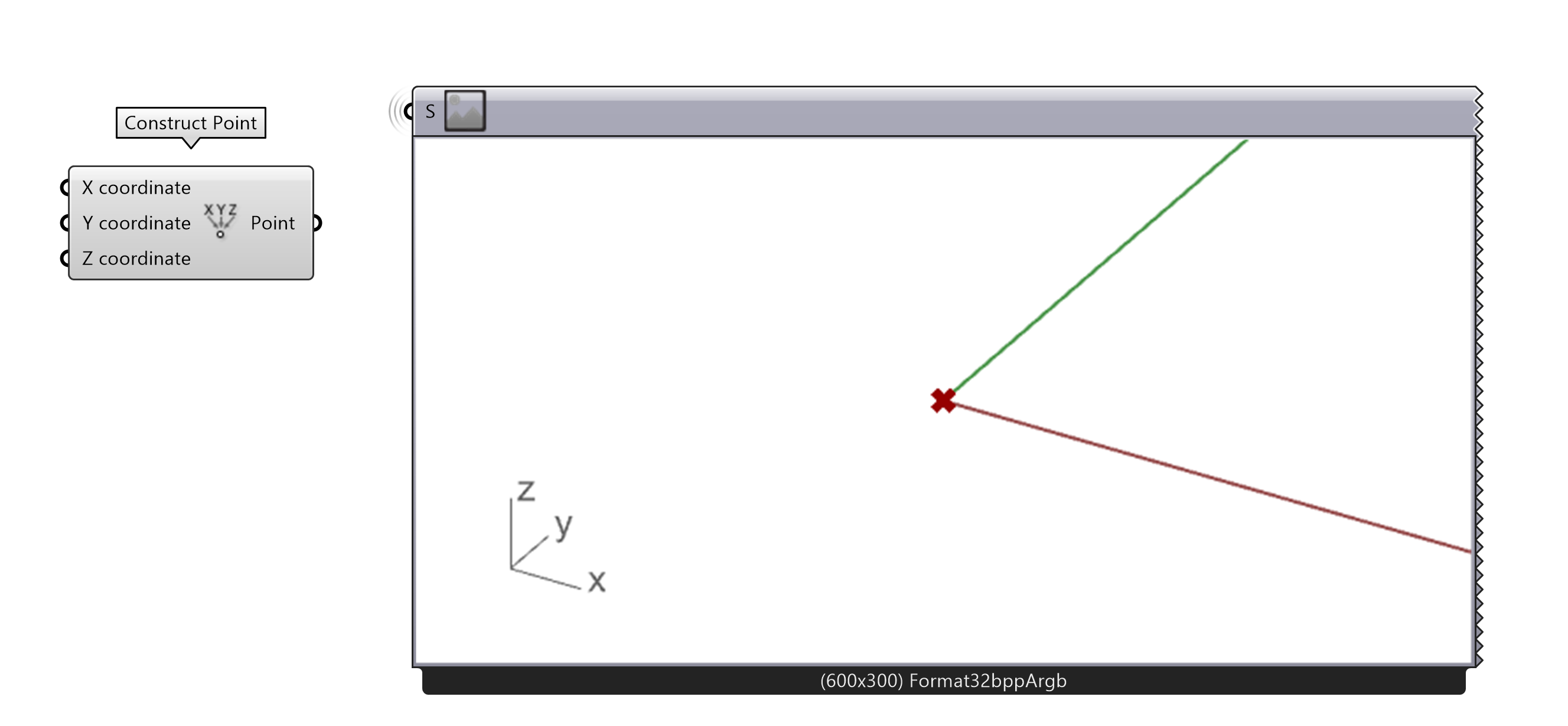
- Create the origin of the grid
The second point will define the direction of the grid. Therefore, a move component is used, this component will move a copy of a geometry or multiple geometries to a certain direction. The direction of the move is defined by a vector. To make a two-dimensional grid we need to define the movement in the X and Y direction. To do this we create an X and Y vector. To combine the two vectors so you create a vector with a X and Y input you must use the addition option. Lastly, the output of the addition must be connected to the move component.
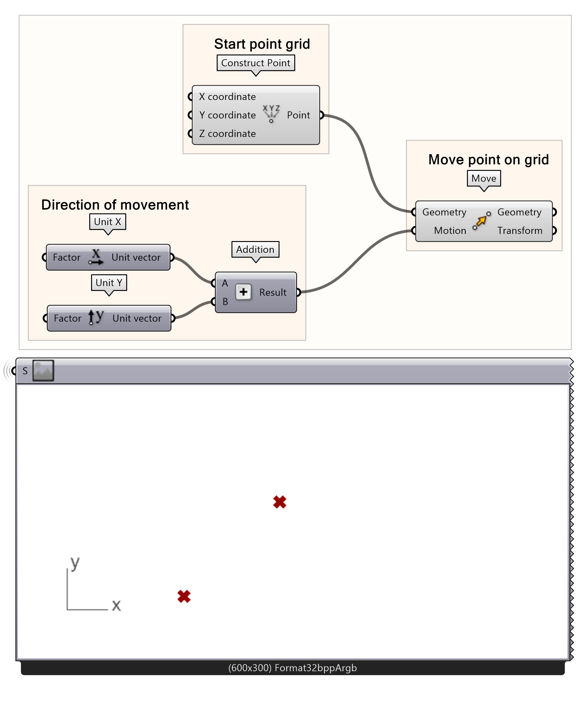
- Connect the origin point to a move function
- Add a Unit X and Unit Y to the canvas
- Connect the unit vectors X and Y to an addition node by
- Put the output in the addition (the motion) in the input of the move node
Diagonal line of points
You can now see two points on your rhino screen, one is the original point, and the other is the moved point. To form a grid, multiple points need to be created in the same direction, this will be done with a series of movement vectors. The series tool in grasshopper can create a series of values with a determined start number, step size and number of values. For more information about how to use series to generate lists you can follow this tutorial:
The basics of the grid is created by setting up the total X and Y dimensions of the grid with a series component. The X and Y dimensions are defined with the size and count of the series. Whereas the step is the distance between each point in the grid and the count the number of points in one direction. Therefore, the grid dimension is the step size multiplied by (the count minus 1). In this example, we will create a rectangular grid of 20×20 meters is created with a step size of 2 meters and 11 points in each direction.
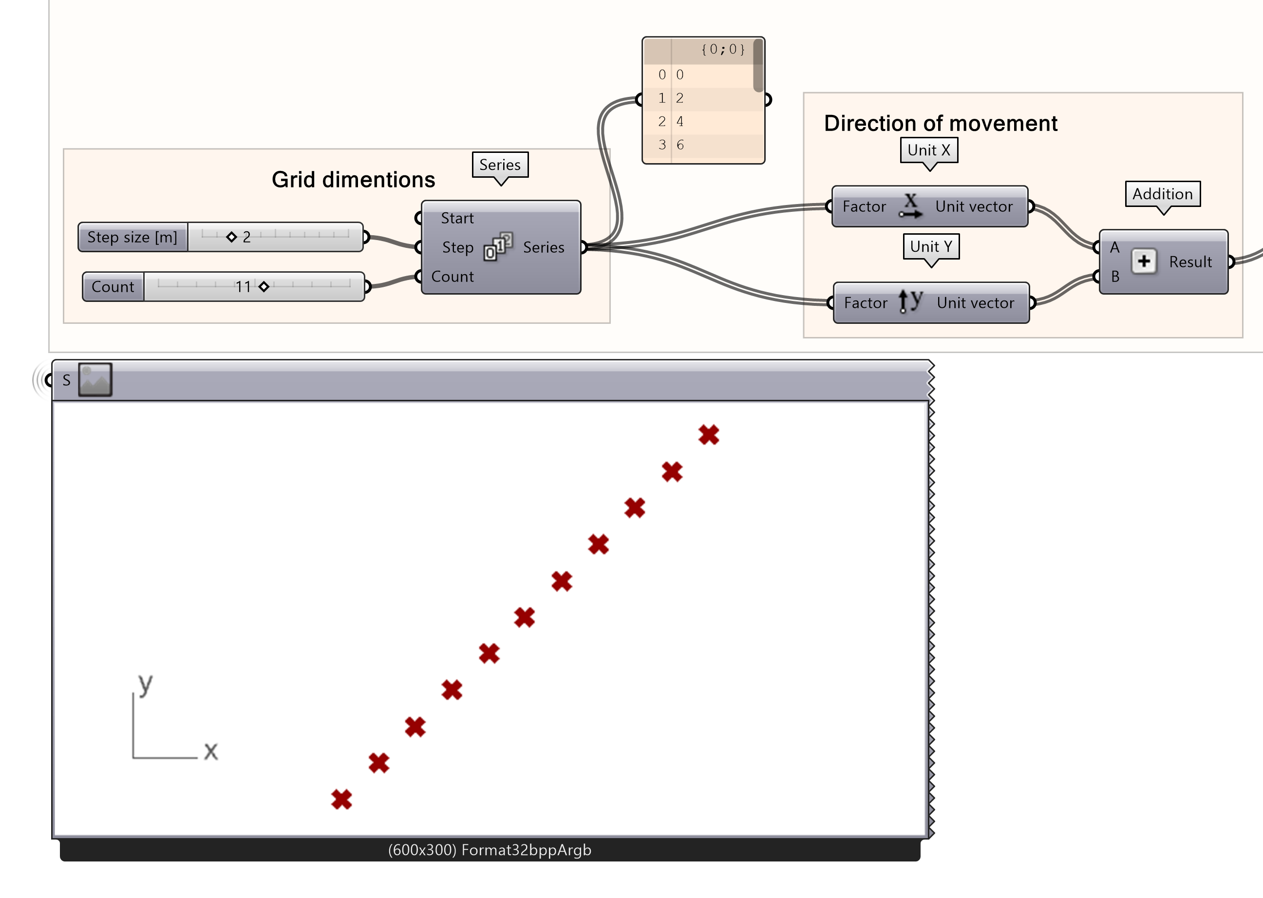
- Connect a series node as input to the unit vectors
- Create two sliders and define the size and count
- Connect the sliders with size and count to the three variables of the series component.
- Connect a panel to the series to show the list of values you just created
Note: If you want to create an irregular grid, you have to make the series component twice with different step sizes and counts and connect each series separately to the X-vector or Y-vector.
Probably you will now see a series of points generated on your screen that are aligned in a straight line. This is still not what we wanted. We want the points to be distributed as a matrix. To do this you have to add a ‘Cross-reference’ component in between. The X and Y-vectors will be cross referenced with the holistic setting, creating two lists of points. One in the X-axis and one on the Y-axis. By adding each point of both list a matrix will be created, this is the point grid. The move component will now distribute the point as a matrix.
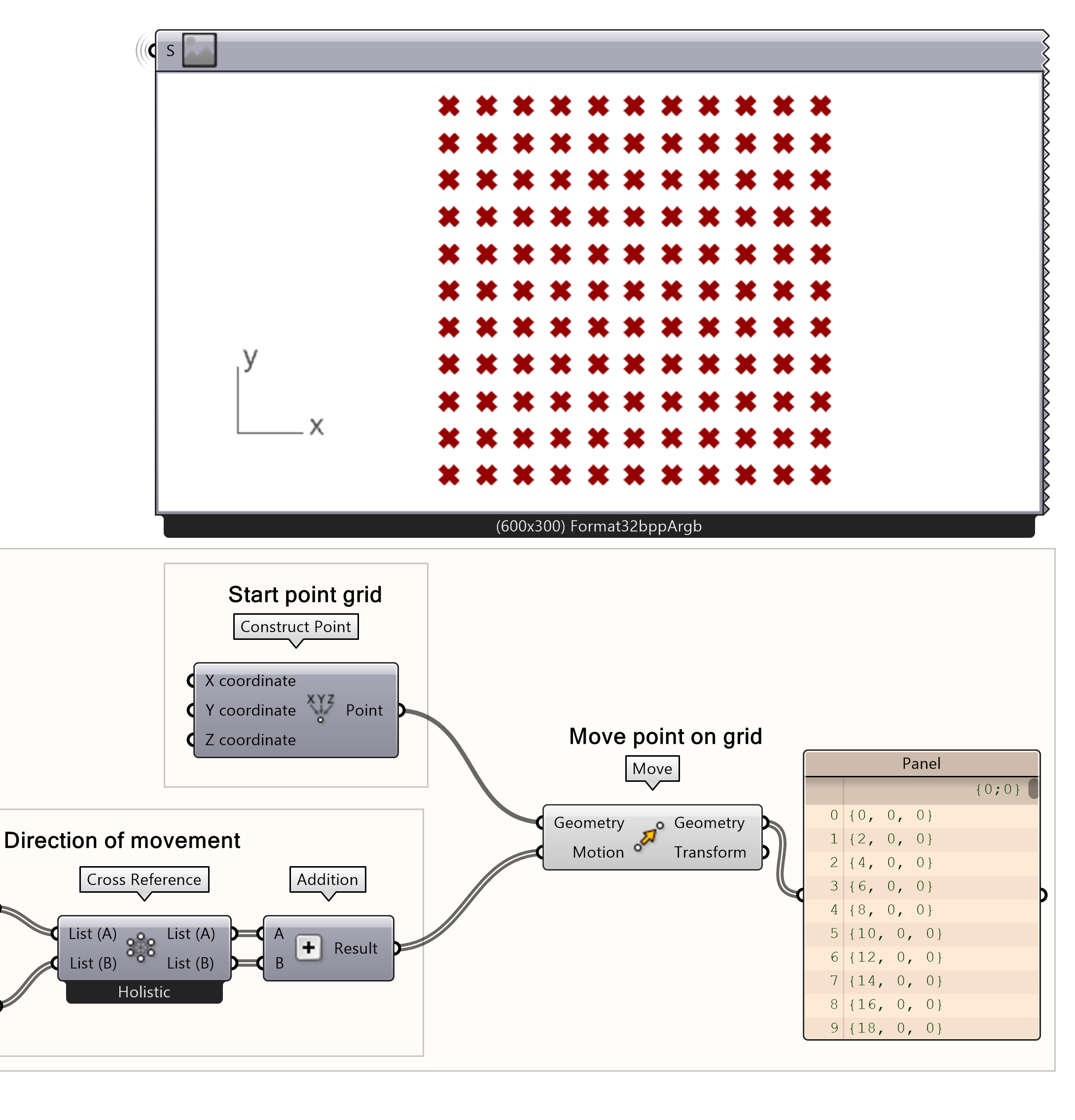
- Make a cross reference between the unit vector X and unit vector Y by
- Add list A to the input A and List B to the input B of the addition component
Creating 2D Grids 3/7
2D grid with rectangularlink copied
Another method to create a 2D point grid is using the rectangular component. This method allows you to create a grid using only one component and number sliders to determine the size and extent of your grid. This part of describes an alternative way to create the same grid and could be skipped.
The rectangular component can be used to create a grid. The start point of the grid created by the rectangular component is defined by the plane input, in which you can input the start of your grid either using a point or a plane. The defaults coordinates of the plane input are 0,0,0. For this tutorial the grid will start at the origin point. By default, an irregular grid is created of 10 by 10 meters with a step size of 1 meter on the X-axis and 2 meters on the Y-axis.
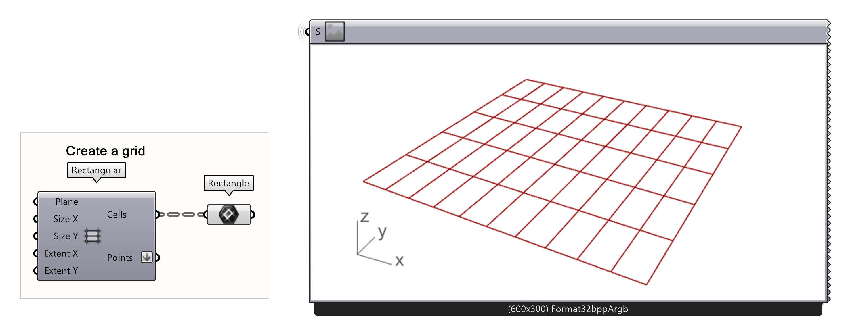
- Create the origin of the grid
The dimensions of the grid can be adjusted by defining the size of each cell in the X and Y direction and the extend, which is the number of times the grid cell is repeated in the X and Y direction. For this example, a 20 by 20-meter square is created with 2 meters between each point in each direction. Therefore, a step size of 2 meters is defined for the X and Y size, and a count of 10 grid cells is defined as extend X and Y.
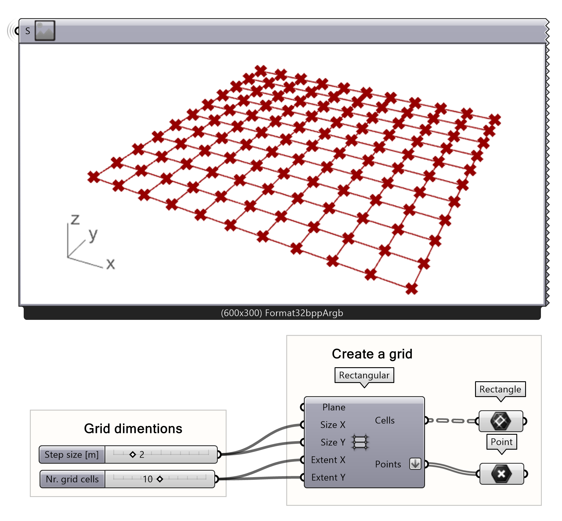
- Set up two number sliders. one with the grid size, and the other one with the extent.
- To preview the grid, you can connect the rectangle component to the cells output:
- To preview the points, you can connect the point component to the points output:
Creating 2D Grids 4/7
Rhino geometry on gridlink copied
Now we have the grid, the only thing left is to populate the grid with columns. There are several options to make the columns. The first option is to create a column in Rhino and place the imported object on the grid points.
First, a geometry must be manually modelled in Rhino, for example a complex geometry like a Roman style column. The geometry can be imported in the Grasshopper canvas by using a geometry component and setting one geometry.
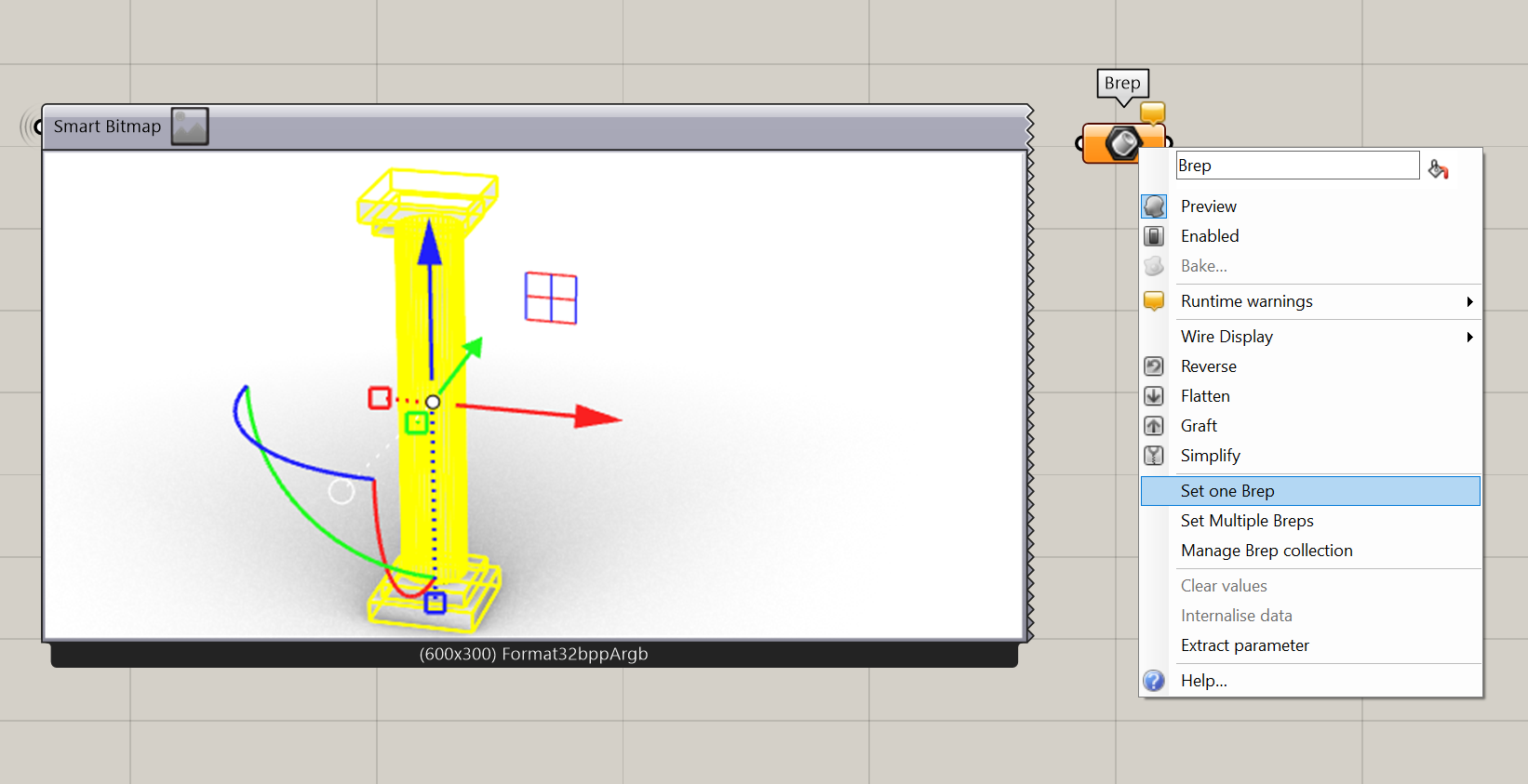
- Create a column in Rhino in the World origin point
- Set the column to a geometry parameter in Grasshopper by choosing
Note: It is important to model the Rhino geometry on the World origin point as this point is used to populate the geometry on the grid. If the bottom center point of the Rhino geometry is not in the World origin, the geometry first must be moved to the World origin before being placed on the grid.
The last step is to place the geometry in the grid. In the 2D grid script with the series method, this can easily be done by replacing the start point of the grid with the geometry. In this way, not the start point will be moved across a grid but the geometry itself.
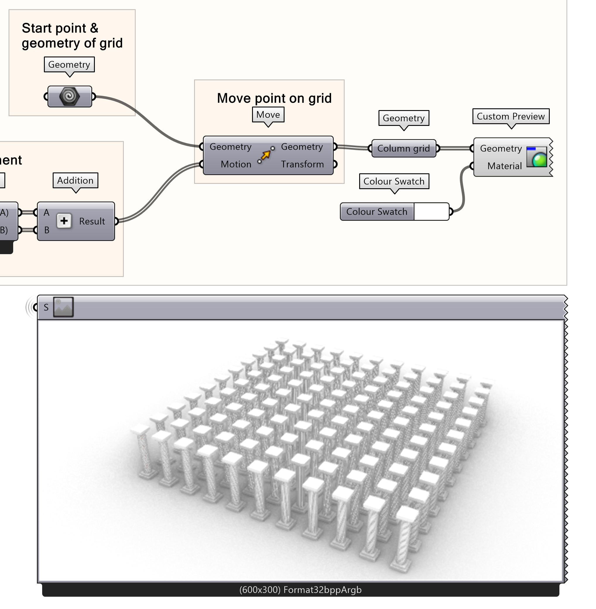
- Replace geometry input of the move component, Construct Point node, with your created column parameter.
Creating 2D Grids 5/7
Parametric column on gridlink copied
The second option is to parametrically make column in Grasshopper and place the geometry on the grid. Depending on the 2D grid creation method the geometry needs to be added differently in the script. For the alternative grid creation option with the rectangular component only the parametric column placement is shown.
Parametric column creation
The first step is to create a parametric column. In this example, we will make a simplified round column with pipe. The parametric column should have a centroid point at the place of the start point of the grid.
We can use our original start point to create our first column. First make the vector that defines the height of the column with the Line SDL component. To make a vertical column we use the z vector.
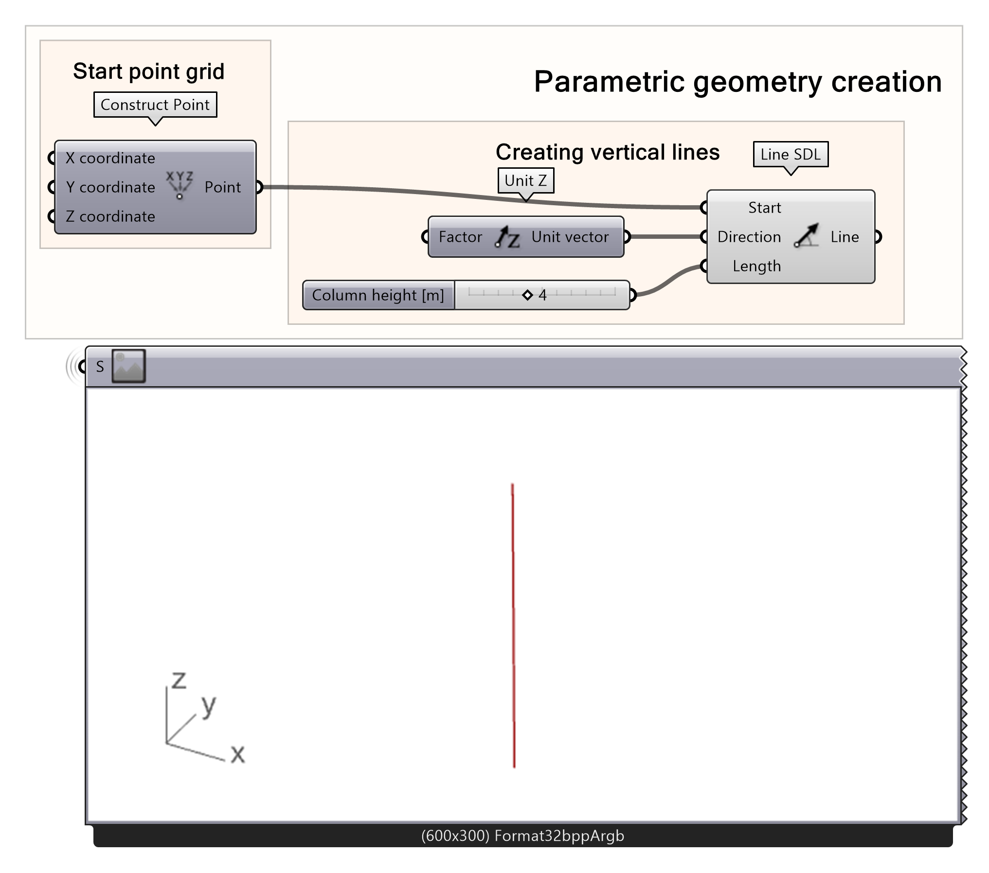
- Add an SDL line node with the created points as input for the Start Curve
- Connect a Unit Z vector to the Direction input
- Connect a number Slider to the length
To create the column, we create a pipe around the vector line. The create line can be used as the rail curve the pipe is created around. Lastly, the column radius and the cap style must be defined. The cap style defines whether the pipe has no cap, a flat cap or a round cap. For this example, the flat cap is used, which is define by the number 1 as input.
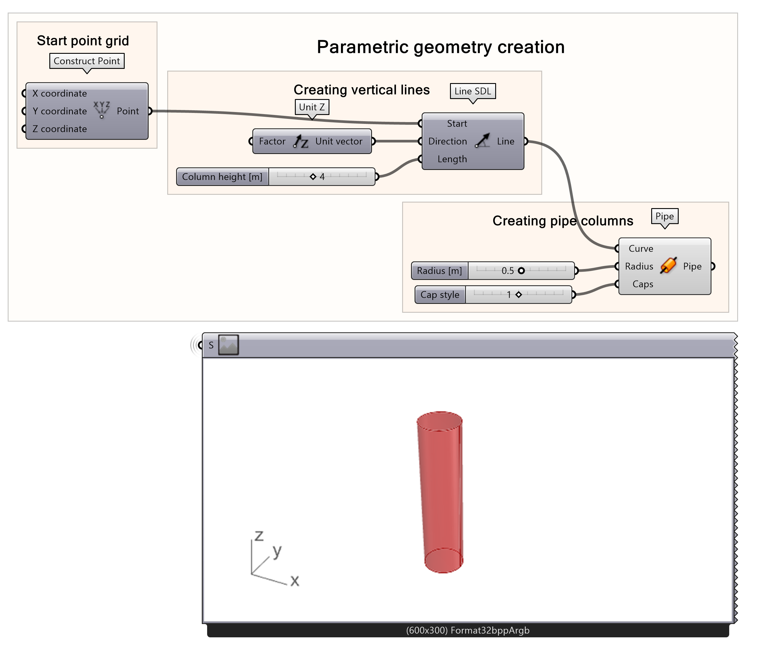
- Create a pipe surface around the SDL Line
- Add a number slider to the Radius input
- Add s number slider to the Caps input
Placing column on grid by series
The last thing step is placing the column on the grid. Depending on the way you created the script, there is a different approach to placing the column on the grid. When you created the 2D grid with the series and move component, the column placement is simple. The starting point of the grid, created with construct point, has to be replaced with the output of the pipe component.
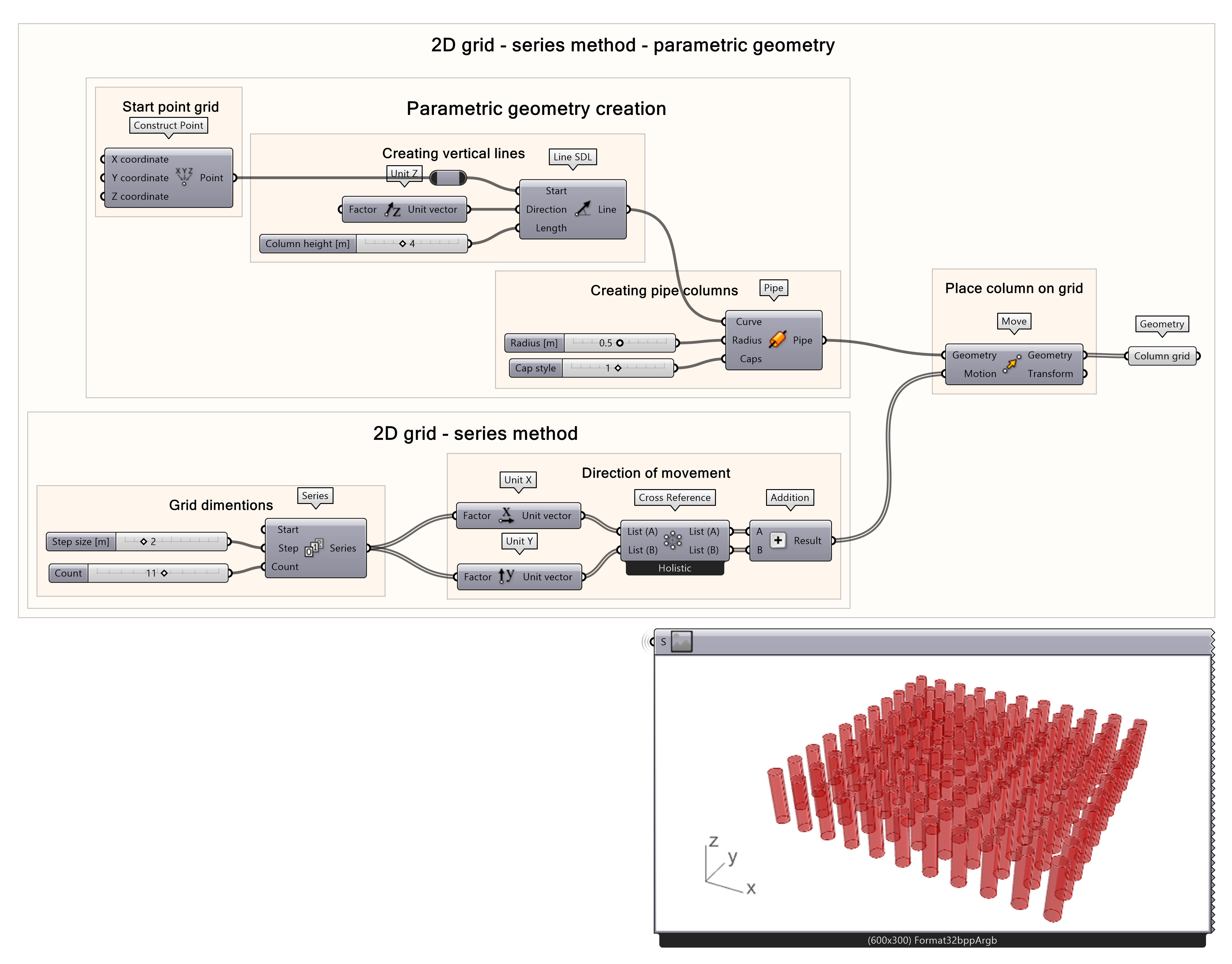
- Replace geometry input of the move component, Construct Point node, with the column geometry from the output of the pipe component
Placing column on grid with rectangular
If you used the grid method with the rectangular component the method of placing the column geometry on the grid is different. With the orient component you can remap a geometry from one axis system to another or place a geometry from an original plane to one or multiple target planes. The created geometry is the input geometry of the orient. The bottom centroid point of the geometry the source plane, which is the start point of the grid. The target are the points of the grid.
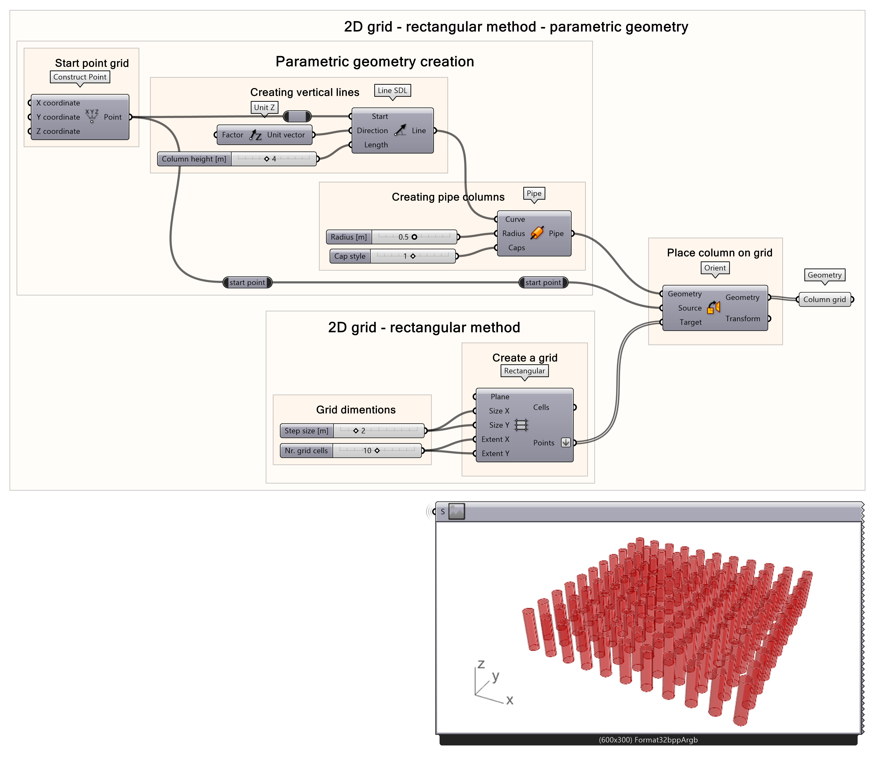
- Add an Orient component by
- Connect your geometry to the geometry input
- Connect the start point of the column to the source input
- Connect the grid points to the target input
Creating 2D Grids 6/7
Conclusionlink copied
This tutorial aims to give a basic overview of how to create 2D grids using two different methods. Upon completing this tutorial, you should be able to create and adjust your own 2D grid and place any type of rhino or grasshopper generated geometry on your grid. This example uses only rectangular or square grids; however, you can start to experiment with different types of grids on grasshopper.
Final Exercise File
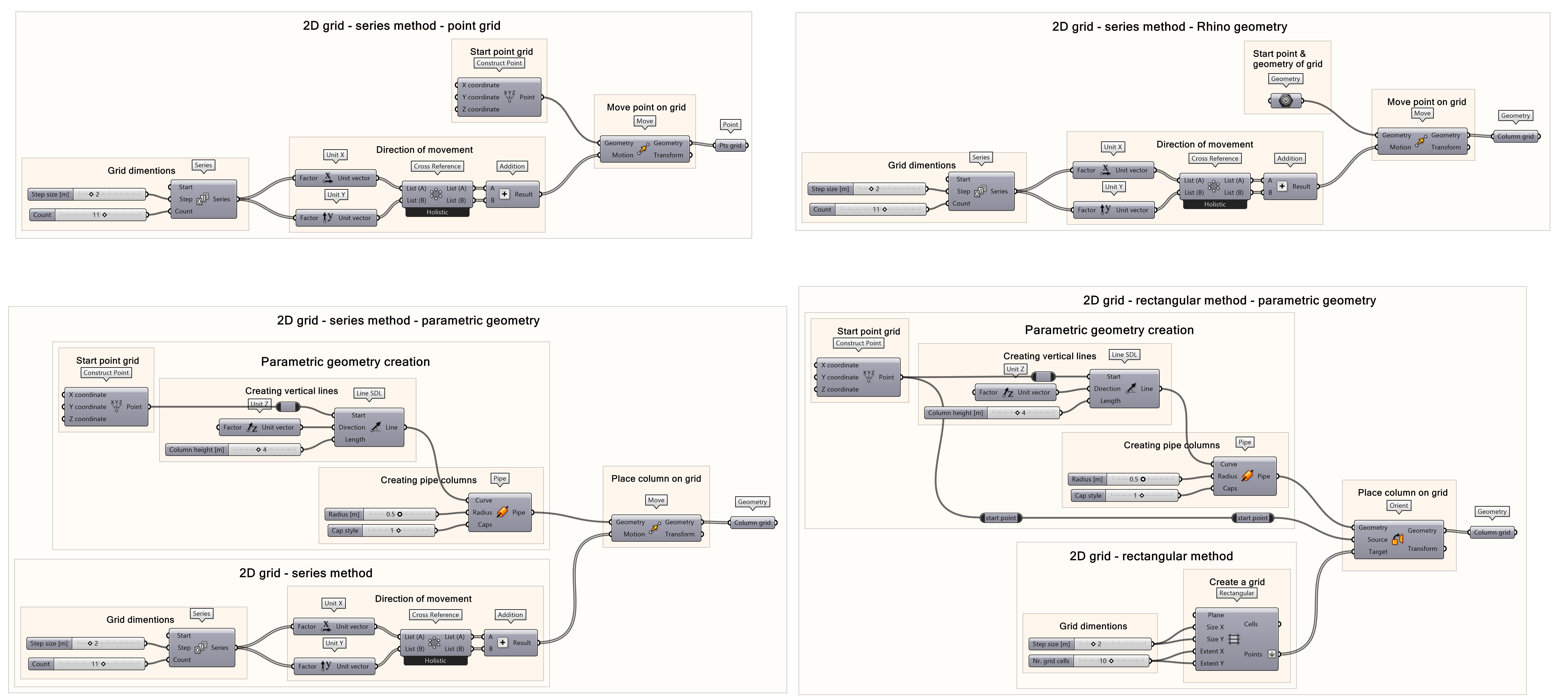
The final script includes 4 script option. The first one creates a 2D point grid, the second one uses a Rhino geometry to create a grid. The third script creates a parametric column and creates the grid with series, just like the first two options. The fourth script uses the rectangular component to create the grid and the parametric column is placed on the grid.
Creating 2D Grids 7/7
Useful Linkslink copied
Linked tutorials
Follow up tutorials
Write your feedback.
Write your feedback on "Creating 2D Grids"".
If you're providing a specific feedback to a part of the chapter, mention which part (text, image, or video) that you have specific feedback for."Thank your for your feedback.
Your feedback has been submitted successfully and is now awaiting review. We appreciate your input and will ensure it aligns with our guidelines before it’s published.
